Method for casting and molding spiral rotor of compressor

A casting molding and compressor technology, which is applied to casting molding equipment, casting molds, casting mold components, etc., can solve problems such as damage to machine tools or cutting tools, waste of metal materials, and increased manufacturing costs, so as to simplify manufacturing procedures and reduce The effect of manufacturing cost and man-hour saving

Inactive Publication Date: 2009-01-14
SHANGHAI HANBELL PRECISE MASCH CO LTD
View PDF0 Cites 11 Cited by
  • Summary
  • Abstract
  • Description
  • Claims
  • Application Information

AI Technical Summary

Problems solved by technology

[0004] As can be seen from the foregoing, the traditional helical rotor manufacturing method is not only time-consuming and labor-intensive, but also wastes metal materials, and because it requires a long time and a large number of cutting operations in the processing process, it is easy to cause damage to machine tools or cutting tools, increasing considerable manufacturing cost

Method used


Image

  • Method for casting and molding spiral rotor of compressor
  • Method for casting and molding spiral rotor of compressor
  • Method for casting and molding spiral rotor of compressor

Examples


Embodiment Construction

[0018] Below in conjunction with accompanying drawing and specific embodiment the present invention is described in further detail:

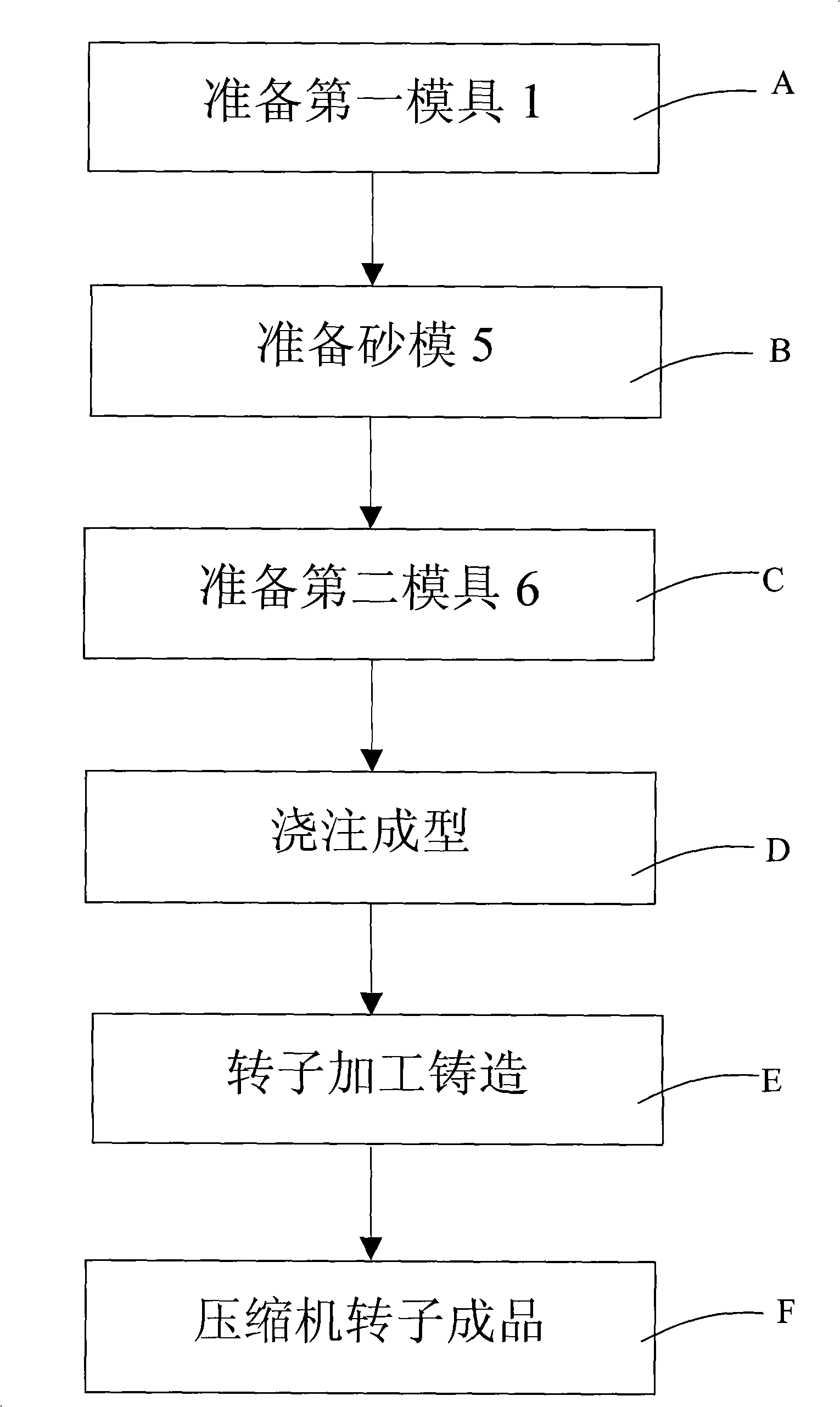
[0019] The present invention is realized through the following steps:

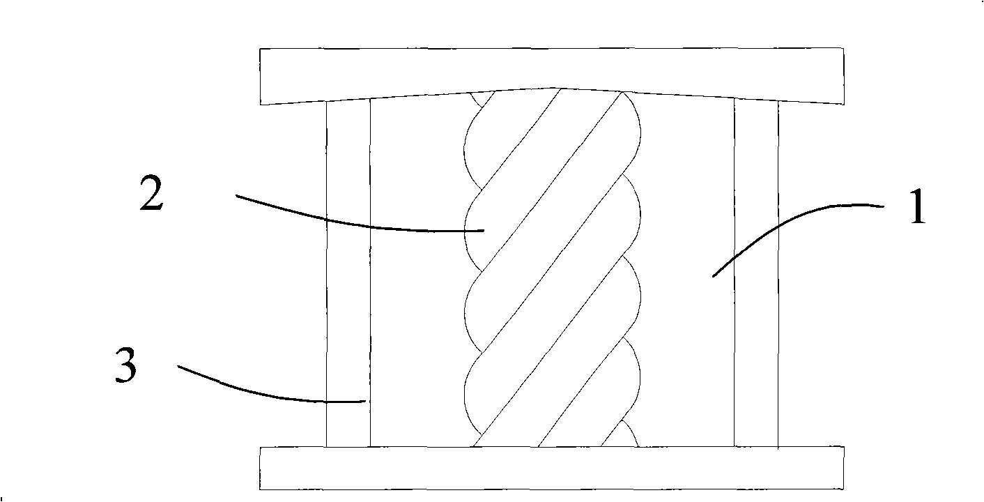
[0020] A, prepare a first mold, and have an axially connected spiral part model in the first mold;

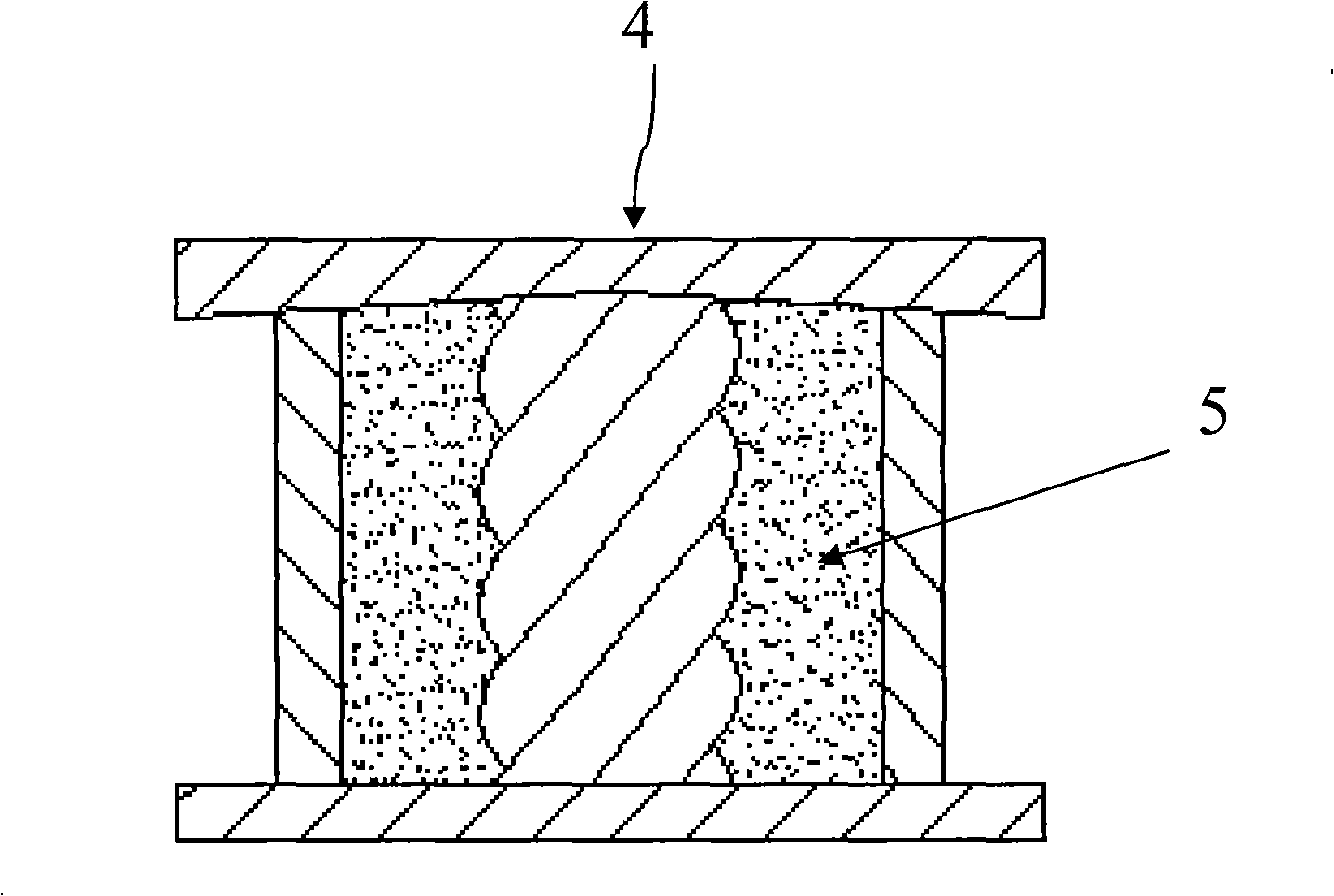
[0021] B. Prepare a sand mold, which is to pour mortar in the above-mentioned first mold, and after the mortar is solidified and shaped, the sand mold is formed after the model is demoulded, and a mold chamber with a spiral portion is formed in it;

[0022] C. Prepare a second mold, the second mold includes an upper sand box and a lower sand box, the sand mold is arranged in the lower sand box, and the upper sand box has a first pivot portion and a second pivot portion Mold cavity, positioning and combining the upper sand box and the lower sand box;

[0023] D. Casting, injecting the liquid casting material into the mold cavity and mold cavity, and after the casting materia...


PUM


Abstract

The present invention relates to a method for casting and forming the helical rotor of a compressor, which is realized through the following steps: preparing a first mould, and a helical part mould is axially arranged inside the first mould; a sand mould is prepared by filling the sand pulp inside the first mould, and after the sand pulp is solidified and formed, the sand mould is formed by removing the mould, and the cast-die cavity of the helical part is arranged inside the sand mould; preparing a second mould: the second mould comprises an upper sand box and a lower sand box, and the sand mould is arranged inside the lower sand box, a molding cavity of a first pivot part and a second pivot part are arranged inside the upper sand box to be fixed and integrated with the upper and the lower sand boxes; pouring and forming: liquid cast-piece material is poured into the cast-die cavity and the molding cavity, and a rotor cast piece that is provided with a helical part and with two ends being respectively connected with the first pivot part and the second pivot part is formed by removing the mould after the cast-piece material is formed; the method of the present invention can save a great amount of materials and can save the manufacturing time.

Description

technical field [0001] The invention relates to a compressor rotor casting molding method, in particular to a casting molding method suitable for manufacturing a compressor screw rotor. Background technique [0002] The rotor is the heart of the compressor, and the manufacturing process of the rotor has a deeper impact on the performance, life, and cost of the overall compressor. Among them, the screw rotor is one of the most widely used rotor types at present, and its application range is quite wide, such as cold coal compressors, air compressors, refrigeration compressors and dry compressors. [0003] However, most of the current screw rotor manufacturing methods are carried out by traditional machining methods, that is, the raw metal materials are cut and sawed into metal blocks, and then the metal blocks are subjected to machine tool cutting, turning and other processing steps, so that Complete the important parts of the helical rotor such as the helical part of the hel...

Claims


Application Information

Patent Timeline
Patent Type & Authority Applications(China)
IPC IPC(8): B22D25/00B22C9/02
Inventor 黄启顺李庆飞
Owner SHANGHAI HANBELL PRECISE MASCH CO LTD
Why Eureka
Try Eureka