
Holder fork parallel move type palletizing mechanical arm

A translational, manipulator technology, applied in the field of palletizing manipulators, can solve the problems of poor palletizing effect of bags, and achieve the effects of stable operation, deformation prevention and easy stacking

Active Publication Date: 2009-01-14
HARBIN BOSHI AUTOMATION
View PDF1 Cites 22 Cited by
  • Summary
  • Abstract
  • Description
  • Claims
  • Application Information

AI Technical Summary

Problems solved by technology

[0003] The purpose of the present invention is to solve the problem that the manipulator used by the existing palletizing robot is particularly soft for the packaging bag, and the fluidity of the material in the bag is particularly good. Palletizing manipulator

Method used


Image

  • Holder fork parallel move type palletizing mechanical arm
  • Holder fork parallel move type palletizing mechanical arm
  • Holder fork parallel move type palletizing mechanical arm

Examples


specific Embodiment approach 1

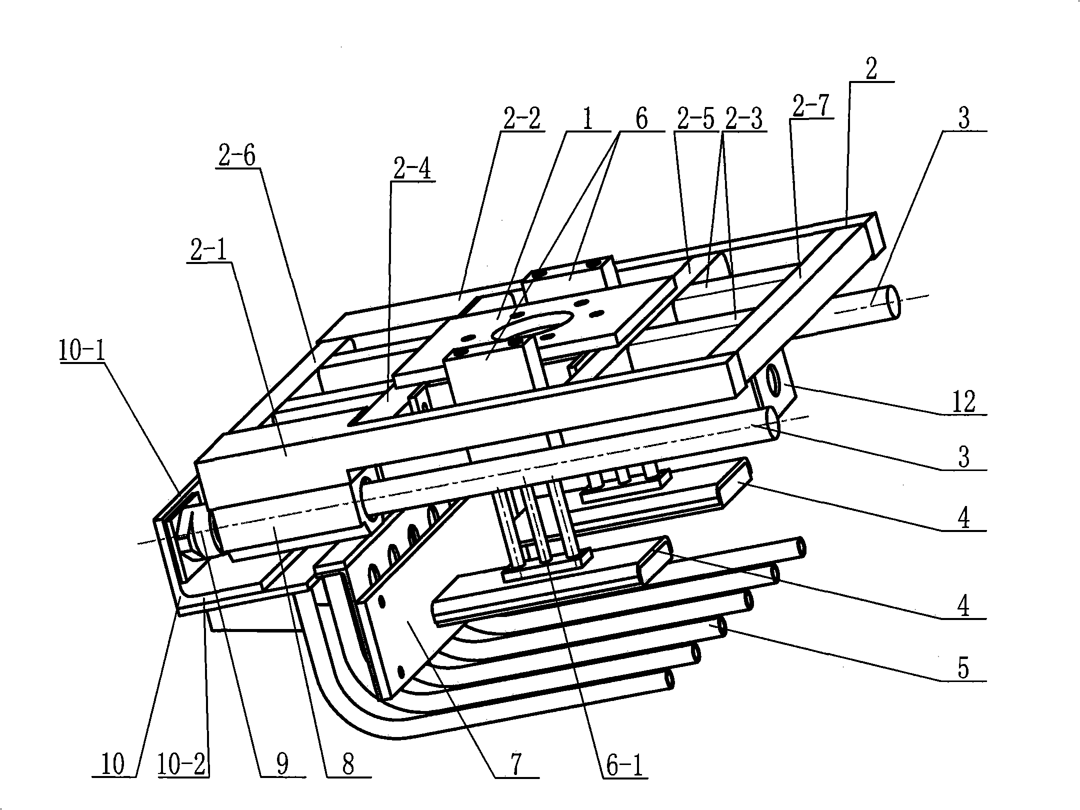
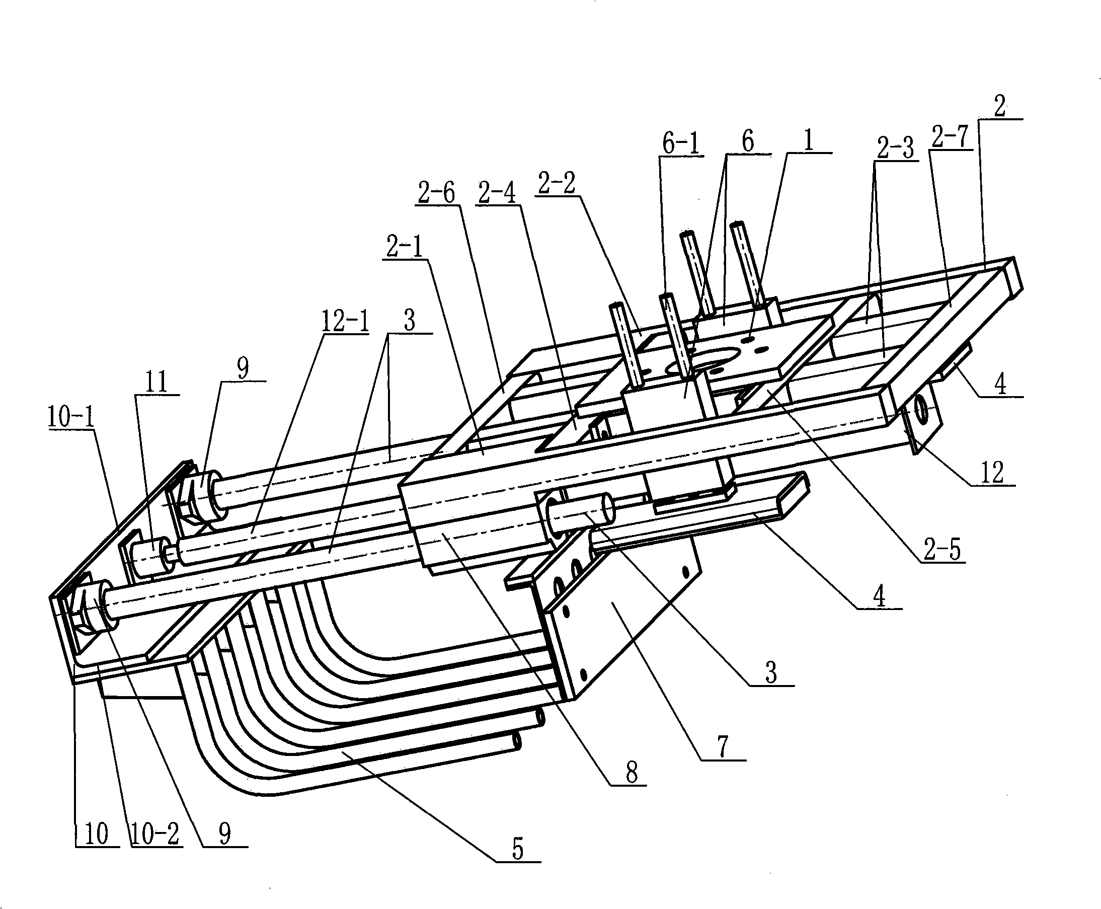
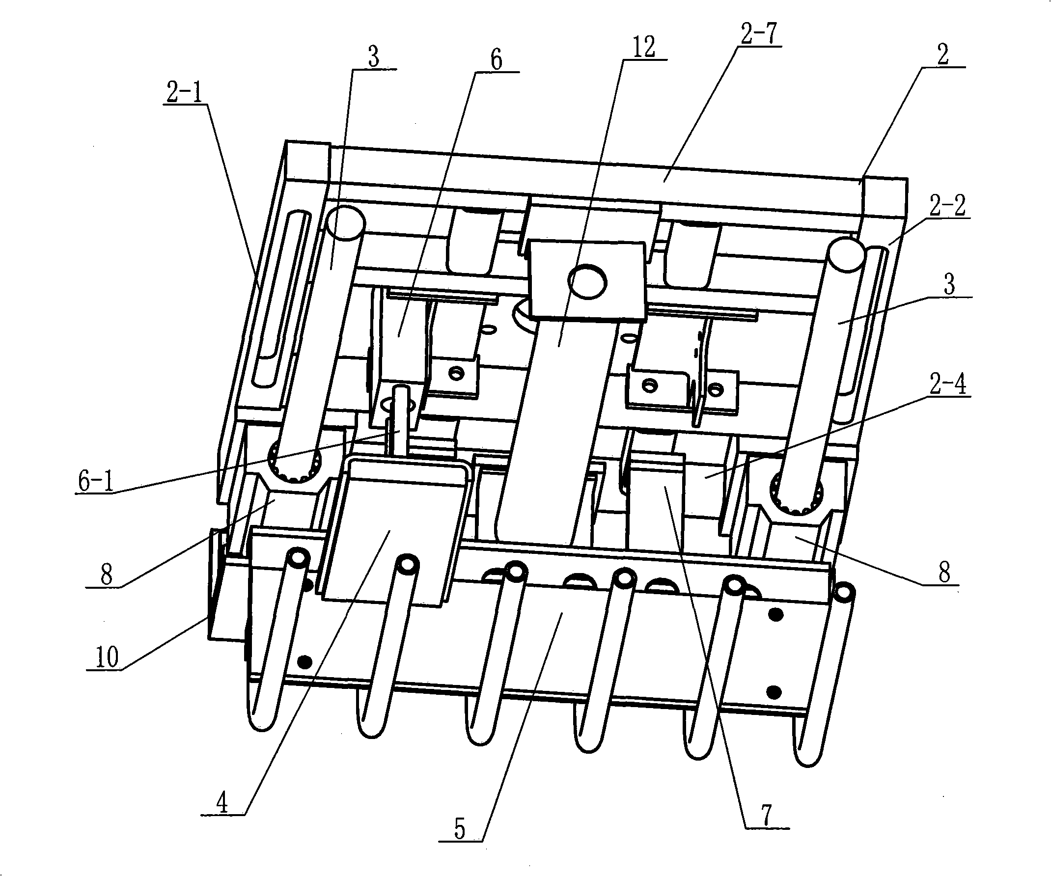
[0007] Specific implementation mode one: combine Figure 1 ~ Figure 3 Describe this embodiment, this embodiment includes flange 1 and frame 2, this embodiment also includes two guide rods 3, two pressure plates 4, support fork 5, two cylinders 6 with guide rods, baffle plate 7, two A linear bearing 8, two supports 9, a bracket 10, a joint 11 and a fork cylinder 12, the flange 1 is installed on the upper end surface of the frame 2, and the two linear bearings 8 are respectively installed on the front of the frame 2 On the lower end faces of the left side of the crossbeam 2-1 and the rear crossbeam 2-2, one ends of the two guide rods 3 pass through two linear bearings 8 respectively and are installed on two supports 9, and the two supports 9 Installed on the right end surface of the vertical plate 10-1 of the support 10 respectively, the two ends of the fork cylinder 12 are respectively installed on the lower end surface of the left longitudinal beam 2-6 and the right longitudin...

specific Embodiment approach 2

[0008] Specific implementation mode two: combination Figure 1 ~ Figure 3 The present embodiment is described. The supporting fork 5 of the present embodiment is composed of 4 to 8 fork rods arranged side by side at equal intervals. Such setting is beneficial to grabbing and stacking operations. Other compositions and connections are the same as in the first embodiment.

specific Embodiment approach 3

[0009] Specific implementation mode three: combination Figure 1 ~ Figure 3 Describe this embodiment, the width of the support fork 5 in this embodiment is equal to the width of the material bag, and the length of the support fork 5 is equal to the length of the material bag. Such setting is beneficial to grabbing and stacking operations. Other compositions and connections are the same as those in the second embodiment.


PUM


Abstract

Disclosed is a support fork translation stacking manipulator which relates to a stacking manipulator. The invention solves the problem of bad stacking effect of the material bag which is very flexible and has the material with good liquidity inside the material bag found in the manipulator used by the stacking robot in the prior art. Two linear bearings (8) of the stacking manipulator are respectively mounted on the lower end surfaces of the front cross beam (2-1) and the back cross beam (2-2) of a frame (2); both ends of a support fork cylinder (12) are respectively mounted on the lower end surfaces of the left stringer (2-6) and the right stringer (2-7) of the frame (2); the cylinder rod of the support fork cylinder (12) is connected with a joint (11); a support fork (5) is mounted on the lower end surface of the transverse plate (10-2) of a support (10); two air cylinders (6) with guide rods are respectively mounted on the inner end surfaces of the front cross beam (2-1) and the back cross beam (2-2) of the frame (2); two pressing plates (4) are respectively mounted on the lower end surface of a guide rod (6-1); a retaining plate (7) is mounted on the lower end surfaces of two middle cross beams (2-3). The support fork translation stacking manipulator has good stacking effect on the material bags which are very flexible and have the materials with good fluidity inside the material bags; the operation of the support fork translation stacking manipulator is stable.

Description

technical field [0001] The invention relates to a stacking manipulator and belongs to the technical field of automation equipment. Background technique [0002] The existing manipulators matched with palletizing robots need to adopt different forms of manipulators for different packaging bags and boxes. Generally, the existing structures such as left and right splint type, four-sided splint type, splint plus fork type, left and right fork type, etc. The manipulators used in the form of palletizing robots can adapt to the palletizing requirements of packaging boxes and most packaging bags. However, for bags that are particularly soft and have particularly good fluidity of the material in the bag, the manipulators with the above-mentioned structural forms cannot achieve a satisfactory palletizing effect. When the left and right splint-type manipulators and the four-side splint-type manipulators clamp the bags, the deformation of the bags will be too large, which will seriousl...

Claims


Application Information

Patent Timeline
IPC IPC(8): B65G61/00B65G57/00B25J15/00
Inventor 宋立志徐忠华魏玉鲁王雪松
Owner HARBIN BOSHI AUTOMATION
Learn More