Plunger type double-ejector rod gas-liquid vat and gas-liquid combination-controlled position and speed servo control device

A technology of double rods and gas-hydraulic cylinders, which is applied in the direction of servo motors, servo motor components, fluid pressure actuators, etc., to achieve the effects of positioning accuracy and rapidity, high precision, and no overshoot accuracy

Inactive Publication Date: 2009-01-14
SOUTH CHINA UNIV OF TECH
View PDF0 Cites 24 Cited by
  • Summary
  • Abstract
  • Description
  • Claims
  • Application Information

AI Technical Summary

Problems solved by technology

The flow of oil removed by the empty plunger rod is less than that of the piston in the existing gas-h

Method used


Image

  • Plunger type double-ejector rod gas-liquid vat and gas-liquid combination-controlled position and speed servo control device
  • Plunger type double-ejector rod gas-liquid vat and gas-liquid combination-controlled position and speed servo control device
  • Plunger type double-ejector rod gas-liquid vat and gas-liquid combination-controlled position and speed servo control device

Examples


Embodiment Construction

[0018] In order to better understand the present invention, the present invention will be further described below in conjunction with the accompanying drawings.

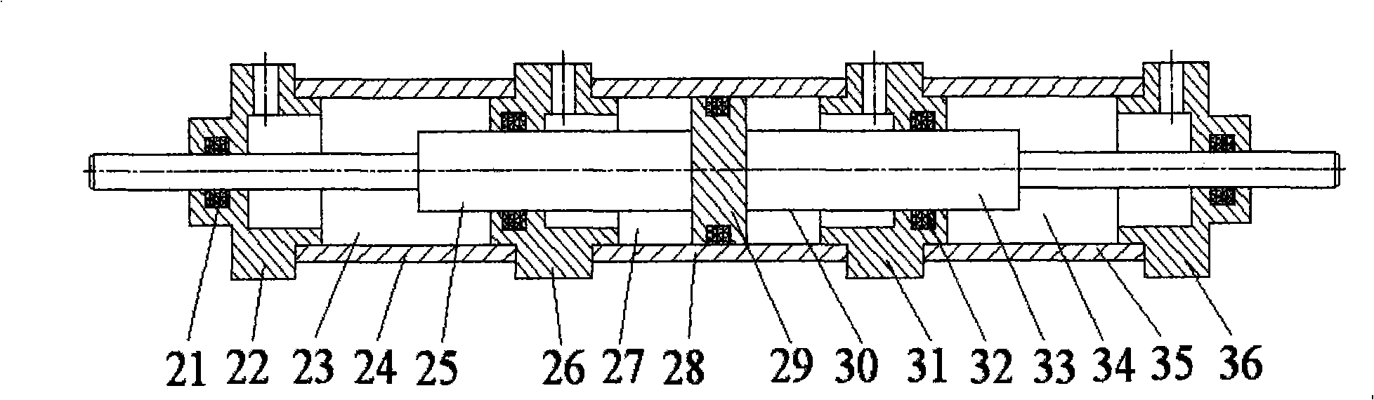
[0019] Such as figure 2 As shown, the plunger-type double-rod air-hydraulic cylinder 8 includes two oil chambers and two air chambers, namely the left oil chamber 23 , the right oil chamber 34 , the left air chamber 27 and the right air chamber 30 . The left oil chamber 23, the right oil chamber 34, the left air chamber 27 and the right air chamber 30 are respectively connected with the outside world through pipelines. The left air chamber 27 and the right air chamber 30 are arranged in the air chamber cylinder 28 and separated by the piston 29. The two ends of the air chamber cylinder 28 are provided with a left air-oil chamber transparent cover 26 and a right air-oil chamber transparent cover 31. Left air-oil chamber see-through cover 26 and right air-oil chamber see-through cover 31 are connected with left oil c...


PUM


Abstract

The invention discloses a plunger-typed double piston rod pneumatic hydraulic cylinder and a gas-liquid joint control position and speed servo control device; the left air cavity and a right air cavity of the plunger-typed double piston rod pneumatic hydraulic cylinder are arranged in an air cavity cylinder barrel and separated by a piston, a left oil chamber and a right oil chamber thereof are respectively arranged in a left oil chamber cylinder barrel and a right oil chamber cylinder barrel; the left and right ends of the piston are respectively connected with a left duty plunger rod and a right duty plunger rod. Two ends of the hydraulic high-speed on-off valve of the gas-liquid joint control position and speed servo control device are respectively connected with the left and right oil chambers; the right duty plunger rod is also connected with a load which is sequentially connected with a displacement sensor, an A/D acquisition card, a computer, a multi-channel D/A converter card, a multi-channel I/O control card and a switching valve driving circuit board. The invention takes the pneumatic supply as the power supply to control the movement of a piston rod pushed by a pneumatic circuit, and carries out the precise position and speed control through inhibiting the vibration of the pneumatic servo caused by the great gas compressibility by the gas-liquid joint control, thus solving the contradiction of positioning accuracy and rapidity.

Description

technical field [0001] The invention relates to a gas-liquid joint control position and speed servo system, in particular to a plunger-type double-rod gas-liquid cylinder and a gas-liquid joint control position and speed servo control device containing the plunger-type double-rod gas-liquid cylinder. Background technique [0002] Pneumatic servo technology is widely used in automated production lines and industries due to its simple structure, low price, energy saving, no pollution, high speed, high efficiency, and easy automation. However, due to the inherent large compressibility and low viscosity of the gas medium itself, the conventional pneumatic servo system has low natural frequency, weak damping, serious nonlinearity, and overshoot in position and speed servo control. Vibration and other problems; the position and speed control accuracy of the air pressure servo system is not high, so the air pressure control system is mostly used for transmission, or in practical ap...

Claims


Application Information

Patent Timeline
IPC IPC(8): F15B11/04F15B11/072F15B11/00F15B15/14F15B13/02
Inventor 邱志成
Owner SOUTH CHINA UNIV OF TECH
Why Eureka
Try Eureka