Check patentability & draft patents in minutes with Patsnap Eureka AI!

Gas magnetic control valve

A control valve, magnetic technology, applied in the valve details, valve device, valve shell structure and other directions, can solve the problems that users are difficult to do, the operation is troublesome, etc., to achieve the effect of opening and closing labor-saving, rapid on-off, and consistent production specifications

Active Publication Date: 2010-06-02
太原天然气有限公司
View PDF7 Cites 0 Cited by
  • Summary
  • Abstract
  • Description
  • Claims
  • Application Information

AI Technical Summary

Problems solved by technology

Now most of the maintenance methods of regular refueling are often used, but the operation feels very troublesome, and it is difficult for users to do it.

Method used


Image

  • Gas magnetic control valve
  • Gas magnetic control valve
  • Gas magnetic control valve

Examples


Embodiment Construction

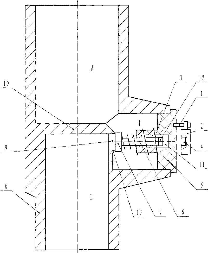
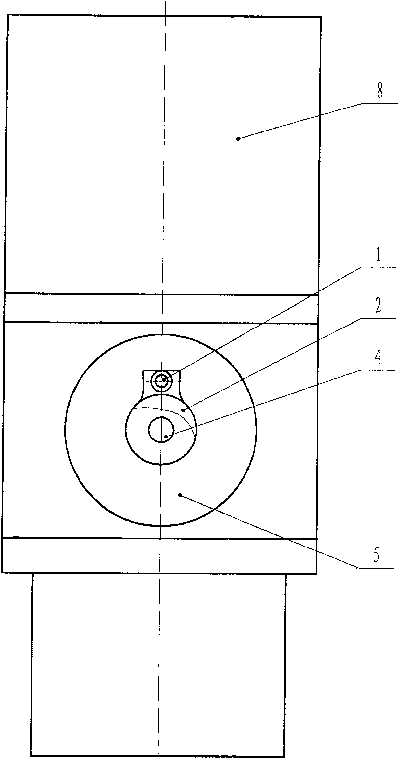
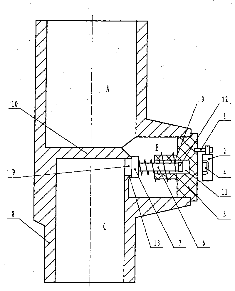
[0012] Such as figure 1 Shown: gas magnetic control valve, mainly includes: valve body 8, valve plate 7, spring 3, magnet and valve stem 4, baffle plate 10 is arranged laterally in the middle of valve body 8, and the upper part of valve body 8 is the air inlet channel A , the lower part of the valve body 8 is the air outlet channel C, the right side of the valve body 8 is the side channel B, the intake channel A and the side channel B communicate freely, the baffle plate 10 and the air outlet channel C form a valve hole 9 on the upper right side, and the side The channel B and the outlet channel C communicate with each other through the valve hole 9, and the valve plate 7 is fixed on the left end of the valve stem 6 in the side channel B, and the valve stem 6 is set to the right in the valve stem sleeve 11 in the T-shaped cover 5, and the spring The left end of 3 is set on one side of the valve stem 6, and withstands the valve plate 7, the valve plate 7 withstands the edge of ...


PUM


Abstract

The invention discloses a gas magnetic control valve which belongs to the control valve technical field of a gas pipeline; the problem to be solved is as follows: providing a gas magnetic control valve, specifically a magnetic control valve with small seal contact area and ring-shaped line contact; controlling the opening or closing manually; providing simple valve manufacturing process with highprecision, good sealing performance and low cost. The proposal adopted is as follows: a valve plate is fixed at the left end of a valve stem in a side channel B; the right end of the valve stem is sheathed inside the valve stem sleeve of a T-typed cover; the left end of a spring is sheathed at one side of the valve stem and leans against the valve plate which leans against the edge of a valve holein the left so as to block the valve hole; the right end of the spring is sheathed outside the valve stem sleeve of the T-typed cover and leans against the left wall of the T-typed cover which is fixed on the channel opening of the side channel B by sealing thread; the outer wall of the top part of the side channel B of the valve body is provided with a rotating plate by a pin; the end of the rotating plate is fixed with an external magnet; the gas magnetic control valve of the invention is suitable to be used indoors and outdoors.

Description

technical field [0001] The gas magnetic control valve of the invention belongs to the technical field of gas pipeline control valves. Background technique [0002] In the field of gas pipeline technology at home and abroad, solenoid valves are often used to control the on-off of gas. In particular, it is very common for gas cookers to use solenoid valves to control gas on-off, and its technology is very mature. For example, some large-scale advanced gas water heater industries in China, All the gas supply systems of gas water heaters use solenoid valves to control the on-off of gas, and the solenoid valves work by generating magnetic fields through energized coils. [0003] For a long time, the indoor valves used in the field of gas technology mainly include plug valves, ball valves, and butterfly valves. The greater the closing resistance. Especially the valve used between the gas pipeline and the gas cooker, due to frequent opening and closing for a period of time, inter...

Claims


Application Information

Patent Timeline
Patent Type & Authority Patents(China)
IPC IPC(8): F16K31/11F16K31/08F16K27/02F24C3/12
Inventor 白天平
Owner 太原天然气有限公司
Features
  • R&D
  • Intellectual Property
  • Life Sciences
  • Materials
  • Tech Scout
  • Unparalleled Data Quality
  • Higher Quality Content
  • 60% Fewer Hallucinations
Learn More