

Blade weight counterbalance test system of aerogenerator
A technology for wind turbines and testing systems, which is applied in the testing of machine/structural components, static/dynamic balance testing, measuring devices, etc. Fast, high test accuracy, simple operation effect
- Summary
- Abstract
- Description
- Claims
- Application Information
AI Technical Summary
Problems solved by technology
Method used
Image

Examples
example 1
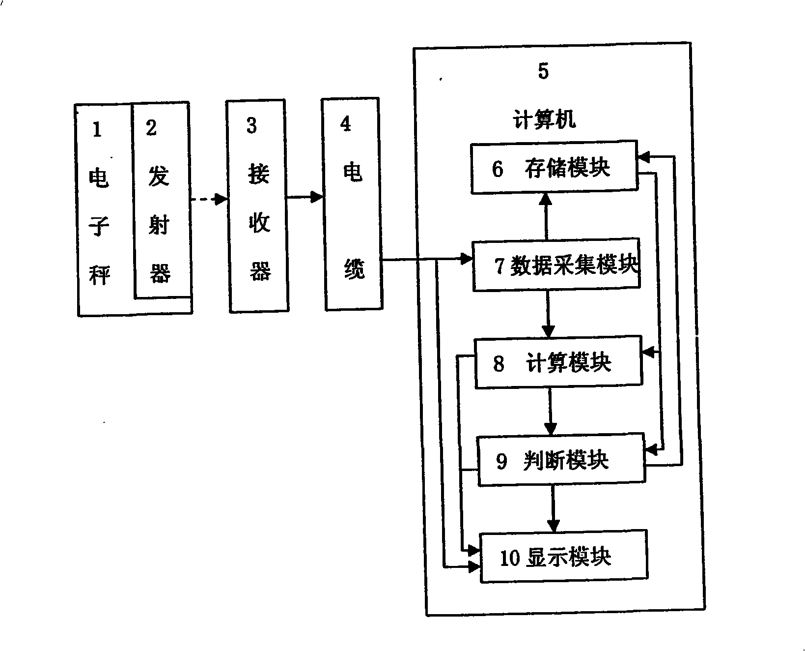
[0021] see figure 1 Summary of the invention: This wind turbine blade counterweight test system mainly includes three parts, one is a weighing device, the other is a weight signal transmission device, and the third is a weight signal processing device.
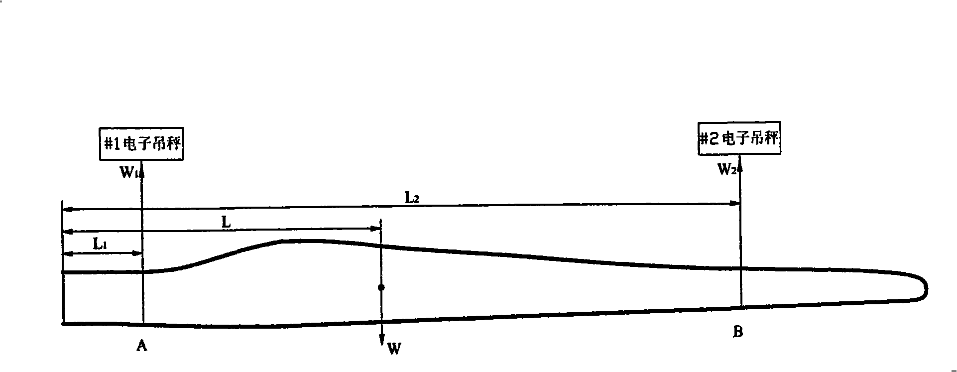
[0022] The weighing device is composed of two sets of electronic crane scales 1, and the electronic crane scale 1 uses the OCS-10Hg-XS wireless digital transmission electronic crane scale, according to figure 1 The two-point weighing is performed as shown, and the weight signal of the blade is converted into a digital electrical signal. See Figure 3 for the weighing principle.
[0023] figure 2 Middle: A and B are the lifting positions of #1 and #2 electronic crane scales, L 1 , L 2 are the distances from A, B to the connecting flange, L is the distance from the center of gravity of the blade to the connecting flange, W 1 , W 2 is the weight measured by the two hanging scales, where W 1 , W 2 , L 1 , L 2 is a known ...
example 2
[0045] Electronic crane scale 1 selects common digital electronic crane scale for use, does not have wireless transmission function, directly connects with computer with signal cable. The rest are the same as example one.
PUM
 Abstract
Description
Claims
Application Information