Open type permanent magnet module with leak stopping structure used for magnetic resonance wave spectrum analyzer
A technology of spectral analysis and magnetic resonance, applied in the field of open permanent magnet modules, can solve the problems of high maintenance cost, large volume and weight, and achieve the effect of low cost, small volume and light weight
- Summary
- Abstract
- Description
- Claims
- Application Information
AI Technical Summary
Problems solved by technology
Method used
Image

Examples
specific Embodiment approach 1
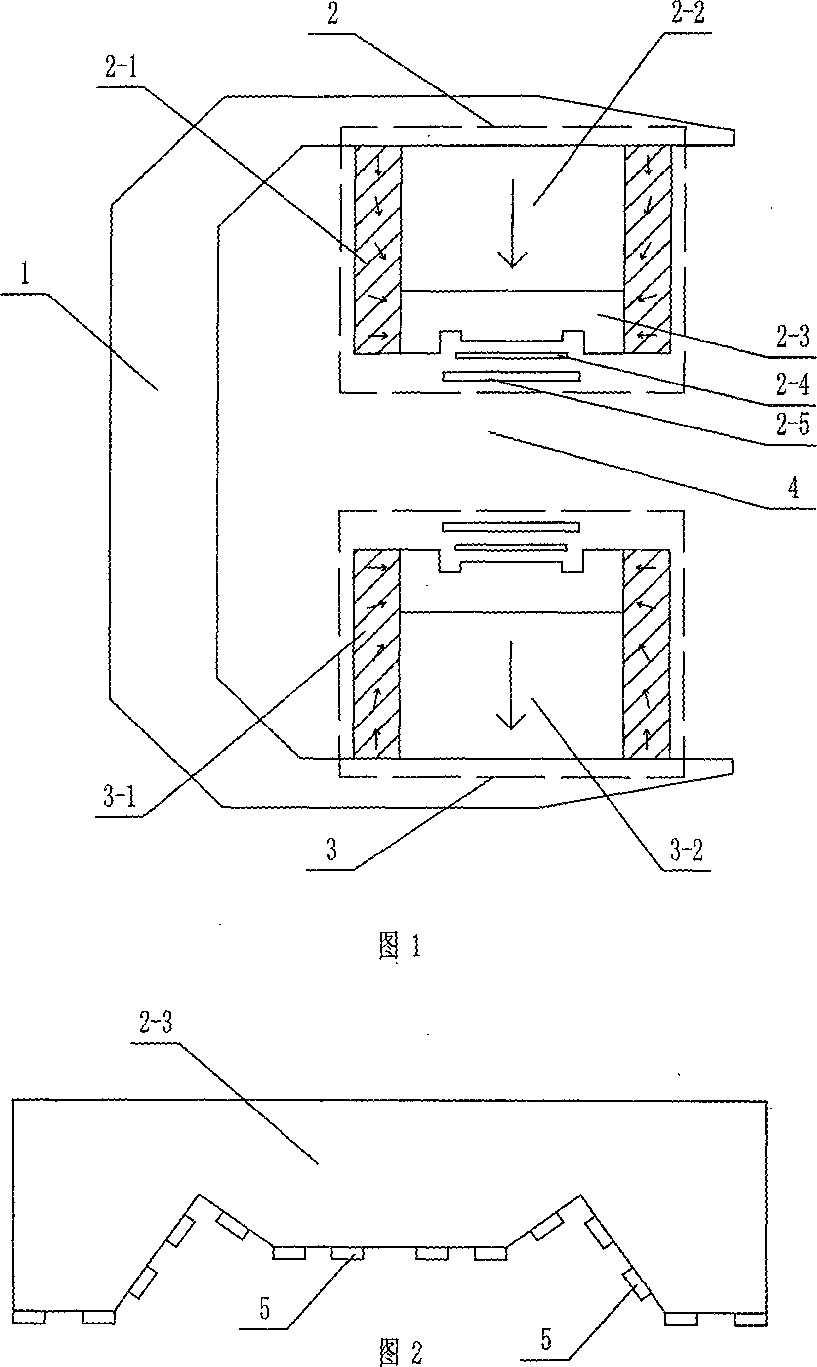
[0006] Specific embodiment 1: Referring to Fig. 1, this embodiment consists of a C-shaped yoke 1, an upper magnet 2 and a lower magnet 3, and the upper magnet 2 consists of an upper ring cylindrical magnetic shell 2-1 and an upper magnetic core 2-2 , magnetic pole 2-3 and shim coil 2-4, the upper ring cylindrical magnetic shell 2-1 is arranged on the lower end surface of the upper arm of the C-shaped magnetic yoke 1, and the magnetization direction of the upper ring cylindrical magnetic shell 2-1 is close to The parallel to the vertical direction of the upper arm of the C-shaped magnetic yoke 1 gradually changes to the perpendicular to the vertical direction close to the imaging space 4, the upper magnetic core 2-2 is arranged in the upper ring cylindrical magnetic shell 2-1 and the upper magnetic core 2- The upper end surface of 2 is arranged on the lower end surface of the upper arm of C-shaped magnetic yoke 1, the magnetization direction of upper magnetic core 2-2 is paralle...
specific Embodiment approach 2
[0008] Specific embodiment two: referring to Fig. 1, the upper magnet 2 and the lower magnet 3 of the present embodiment have increased gradient coils 2-5 respectively on the basis of specific embodiment one, and two gradient coils 2-5 are respectively arranged in the imaging space 4 In the position close to the magnetic pole surface. Part of the shimming function of the shimming coil can be realized by the gradient coil 2-5, the shimming coil 2-4 and the gradient coil 2-5 are all arranged in the imaging space 4 near the magnetic pole surface, and the shimming coil 2- 4 Relatively close to the magnetic pole 2-3 or the gradient coil 2-5 relatively close to the magnetic pole 2-3 can increase the shimming accuracy, and some non-magnetic permeability can be filled between the gradient coil 2-5 and the shim coil 2-4 substance.
specific Embodiment approach 3
[0009] Embodiment 3: Referring to FIG. 2 , this embodiment adds a plurality of magnetic sheets 5 on the basis of Embodiment 1, and each magnetic sheet 5 is respectively arranged on the surface of the magnetic pole 2 - 3 near the end of the imaging space 4 . The magnetic sheet 5 is used for shimming, and the magnetic sheet 5 may be partially or completely replaced by an iron sheet.
PUM
 Abstract
Description
Claims
Application Information
 - R&D
- Intellectual Property
- Life Sciences
- Materials
- Tech Scout
- Unparalleled Data Quality
- Higher Quality Content
- 60% Fewer Hallucinations
Browse by: Latest US Patents, China's latest patents, Technical Efficacy Thesaurus, Application Domain, Technology Topic, Popular Technical Reports.
© 2025 PatSnap. All rights reserved.Legal|Privacy policy|Modern Slavery Act Transparency Statement|Sitemap|About US| Contact US: help@patsnap.com