
Conversion coupling device for prosthetic limbs

A technology of a coupling device and a conversion device, applied in the field of prosthetics

Active Publication Date: 2011-12-07
OTTO BOCK HEALTHCARE IP GMBH & CO KG
View PDF0 Cites 0 Cited by
  • Summary
  • Abstract
  • Description
  • Claims
  • Application Information

AI Technical Summary

Problems solved by technology

Likewise, the grabbing and opening of the hands requires separate gearing

Method used


Image

  • Conversion coupling device for prosthetic limbs
  • Conversion coupling device for prosthetic limbs
  • Conversion coupling device for prosthetic limbs

Examples


Embodiment Construction

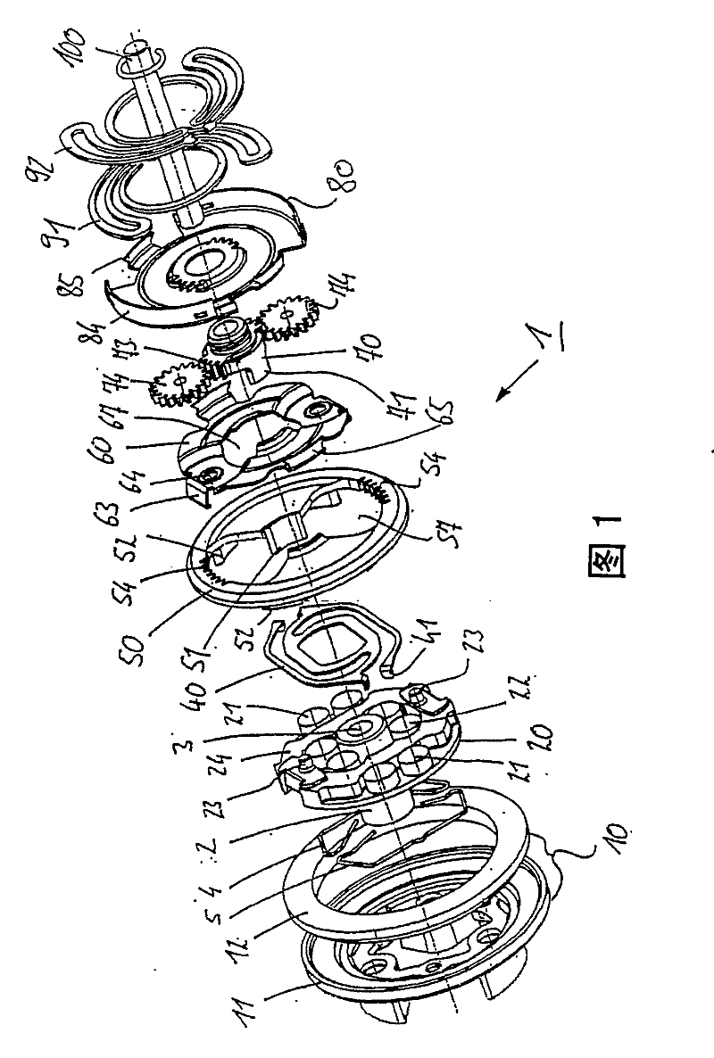
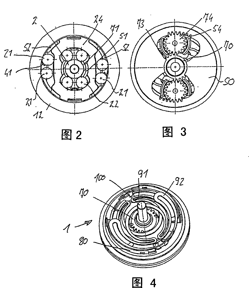
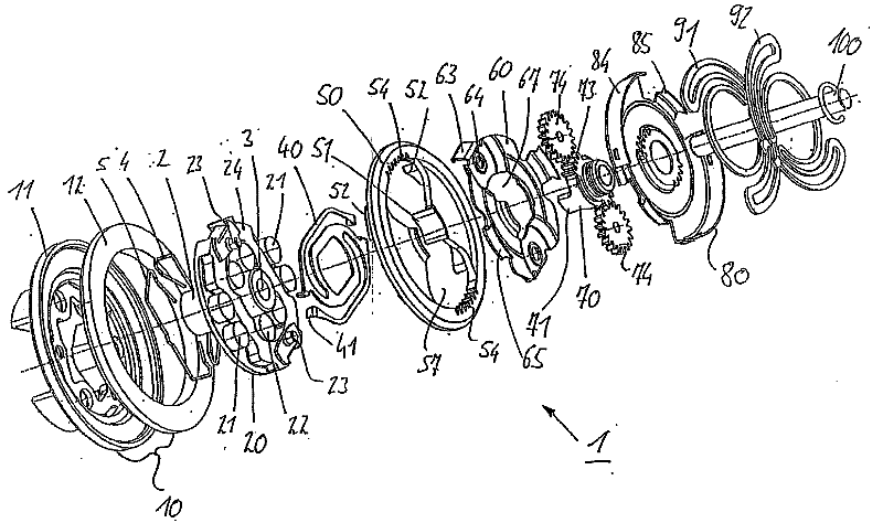
[0018] figure 1 The conversion coupling 1 is shown in an exploded view. The shifting coupling 1 is used for torque-controlled shifting between a high-speed gear and a power gear and has a drive shaft 2 on which a drive disc 20 is movably arranged. The drive plate 20 is mounted rotatably in the planetary carrier housing 10 . A planetary gear, a harmonic drive or another high-ratio gear, which is not shown for reasons of clarity, is located inside the planetary carrier housing. The planet carrier housing 10 has a contact ring 12 on whose inner circumference the running surface is formed. For reasons of stability, the contact ring 12 is solid and preferably consists of steel. As an alternative, the running face of the contact ring 12 can consist of a hardened steel ring and form the running face. Underneath the contact ring 12 is molded a plastic housing 11 which, for reasons of weight, is preferably made of plastic. Contact ring 12 and housing 11 can be fastened to one ano...


PUM


Abstract

The invention relates to a clutch module for prostheses, in particular for prosthetic grippers, arm prostheses or hand prostheses that comprise a chassis to which at least one finger prosthesis is articulated, the clutch module including a drive element, a driven element and a clutch device, which shifts between two gear stages depending on the torques applied to the driven element.

Description

technical field [0001] The invention relates to a conversion coupling for a prosthesis, in particular for a prosthetic grasping device, a prosthetic arm or, for example, a prosthetic hand, for example, with a base on which at least one prosthetic finger is articulated, so that The shifting coupling has a drive element, an output element and a shifting device, which shifts between two transmission stages depending on the torque acting on the drive element. Background technique [0002] In order to be able to achieve high gripping forces on the one hand and fast gripping movements on the prosthetic element, prosthetic hand, prosthetic arm or prosthetic gripping element on the other hand, a transmission is provided in the prosthesis, which on the one hand enables high In order to quickly contact the object to be gripped, and on the other hand also have a small transmission ratio in order to achieve a correspondingly high gripping force. The shifting between the individual gea...

Claims


Application Information

Patent Timeline
Patent Type & Authority Patents(China)
IPC IPC(8): F16H3/00A61F2/68
CPCA61F2/68A61F2/54A61F2002/30518A61F2002/30527A61F2002/6845F16H61/0295A61F2220/0025A61F2/583A61F2002/30523A61F2/70
Inventor G·普奇哈默
Owner OTTO BOCK HEALTHCARE IP GMBH & CO KG
Learn More