Helical-conveyer centrifugal

A screw discharge and centrifuge technology, applied in the field of centrifuges, can solve the problems of poor wear resistance, increase manufacturing costs, and troublesome processing, achieve separation effect guarantee, improve solid-liquid separation effect, and prolong service life. Effect

Inactive Publication Date: 2009-01-21
JIANGSU HUADA CENTRIFUGE
View PDF0 Cites 10 Cited by
  • Summary
  • Abstract
  • Description
  • Claims
  • Application Information

AI Technical Summary

Problems solved by technology

When this kind of centrifuge separates the slurry with less homogeneous content, the separation effect is poor because the solid phase components in the slurry cannot be sufficiently settled; in addition, due to the large volume of the pusher blade, if the whole body is used Expensive wear-resistant materials (such as cemented carbide), on the one hand, are troublesome to process, and on the other hand, increase the manufacturing cost; therefore, the current pusher blades are usually made of ordinary materials, and their wear resistance is not very good , after using for a period of time, the facing surface at the end of the pusher blade will be worn, which will affect the separation effect of the centrifuge

Method used


Image

  • Helical-conveyer centrifugal
  • Helical-conveyer centrifugal

Examples


Embodiment Construction

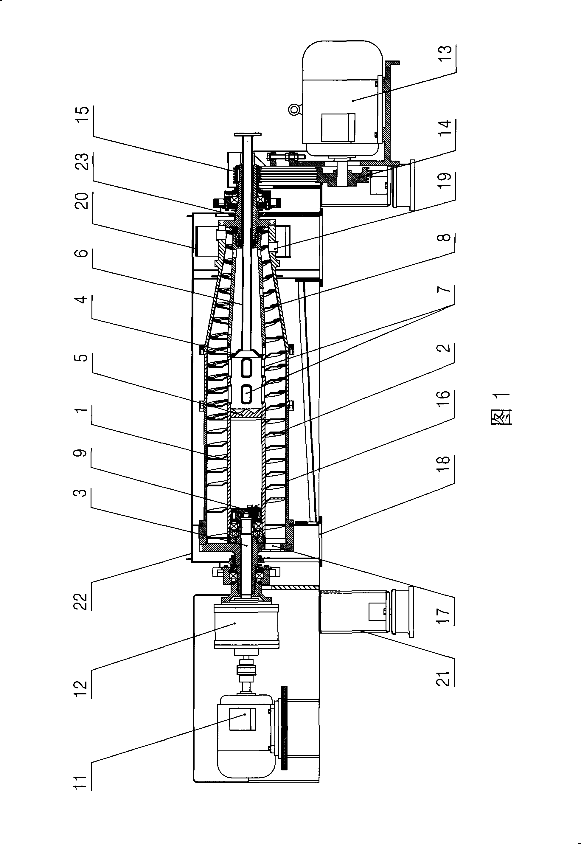
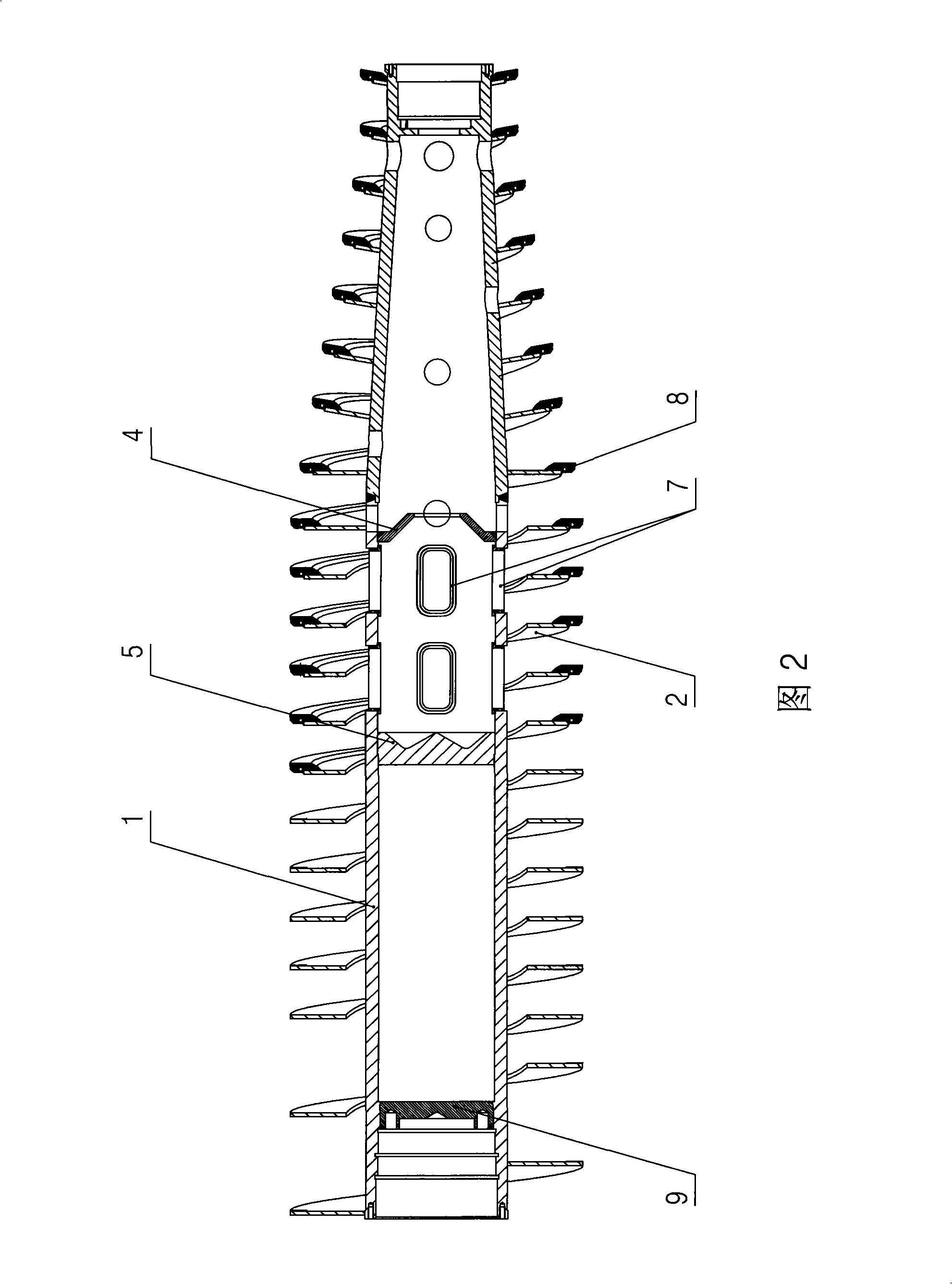
[0012] As shown in Figure 1, the screw discharge centrifuge of the present invention comprises: feed pipe 6 and support 21, on support 21, be provided with rotating drum 16 through bearing activity, be provided with in rotating drum 16 through bearing activity Pushing device, machine base 21 is also provided with organic casing 22, differential drive device and main shaft drive device, drum 16 is covered in casing 22, and drum 16 is connected with main shaft drive device through drum shaft 23, described The pushing device includes: a hollow spiral mandrel 1, the bottom of the spiral mandrel 1 is provided with a transmission shaft 3 - the transmission shaft 3 extends into the installation cavity at the bottom of the spiral mandrel 1, and is fixed with the bottom plate 9, the transmission The shaft 3 is connected to the differential drive device, and the front and rear parts of the outer wall of the spiral mandrel 1 are respectively provided with a spiral pusher blade 2, and the ...


PUM


Abstract

The invention discloses a spiral discharge centrifuge which can ensure slurry to get the full settlement in a rotary drum of the centrifuge, the spiral discharge centrifuge comprises: a feed pipe and a machine base, the rotary drum is movably arranged on the machine base, a pushing device is movably arranged in the rotary drum, the rotary drum is covered in a machine shell, the rotary drum is connected with a main shaft drive device through a shaft of the rotary drum, the pushing device comprises a hollow spiral core shaft, a transmission shaft is arranged at the bottom part of the spiral core shaft, the transmission shaft is connected with a differential drive device, two spiral pushing blades are arranged on the outer wall of the spiral core shaft, front and back stop plates are arranged in the middle of the inner cavity thereof for forming a feed chamber, a feed inlet is arranged in the front stop plate, a passing port is arranged on the side wall of the feed chamber; the feed pipe is connected with the feed inlet, an overflow port is arranged at the bottom part of the rotary drum, the overflow port is communicated with a liquid discharge port which is arranged at the bottom part of the machine shell; and a discharge outlet which is arranged on the rotary drum is communicated with a material discharge port which is arranged at the bottom part of the machine shell. The spiral discharge centrifuge is especially applicable to the separation of the slurry with less solid-phase content.

Description

technical field [0001] The present invention relates to centrifuges, in particular to screw discharge centrifuges. Background technique [0002] As we all know, a pusher is arranged in the drum of the screw discharge centrifuge, and its structure includes: a spiral mandrel, and a spiral pusher blade is arranged on the spiral mandrel. The function of the pushing blade is to push the dehydrated material out of the drum. When this kind of centrifuge separates the slurry with less homogeneous content, the separation effect is poor because the solid phase components in the slurry cannot be sufficiently settled; in addition, due to the large volume of the pusher blade, if the whole body is used Expensive wear-resistant materials (such as cemented carbide), on the one hand, are troublesome to process, and on the other hand, increase the manufacturing cost; therefore, the current pusher blades are usually made of ordinary materials, and their wear resistance is not very good After...

Claims


Application Information

Patent Timeline
IPC IPC(8): B04B1/20B04B11/04B04B9/02
Inventor 吴志明屠文学史学礼蔡宏杜继伟
Owner JIANGSU HUADA CENTRIFUGE
Why Eureka
Try Eureka