Eureka AIR delivers breakthrough ideas for toughest innovation challenges, trusted by R&D personnel around the world.

Device for adjusting knife door of numerical control hydraulic double-clamp veneer lathe

A technology of adjusting device and rotary cutting machine, which is applied in the manufacture of thin wood chips, wood processing appliances, manufacturing tools, etc., can solve the problems of low work efficiency, low adjustment precision, troublesome operation, etc., and achieves high work efficiency and high adjustment precision. , the effect of simple operation

Active Publication Date: 2009-01-21
SHANDONG BAISHENGYUAN GRP
View PDF0 Cites 6 Cited by
  • Summary
  • Abstract
  • Description
  • Claims
  • Application Information

AI Technical Summary

Problems solved by technology

[0003] The technical problem solved by the present invention is to solve the problem that the knife door cannot be adjusted in the working state. When the thickness of the veneer is changed every time, it is necessary to close the numerical control hydraulic double-spindle rotary cutter first, and then manually adjust the knife door, which is troublesome to operate. To solve the problems of low precision and low work efficiency, provide a CNC hydraulic system that can adjust the knife door under the working state of the rotary cutting machine. When the thickness of the rotary cutting veneer changes, there is no need to shut down the machine. The operation is simple, the adjustment precision is high, and the work efficiency is high Adjusting device for knife door of double card shaft rotary cutting machine

Method used


Image

  • Device for adjusting knife door of numerical control hydraulic double-clamp veneer lathe
  • Device for adjusting knife door of numerical control hydraulic double-clamp veneer lathe

Examples


Embodiment Construction

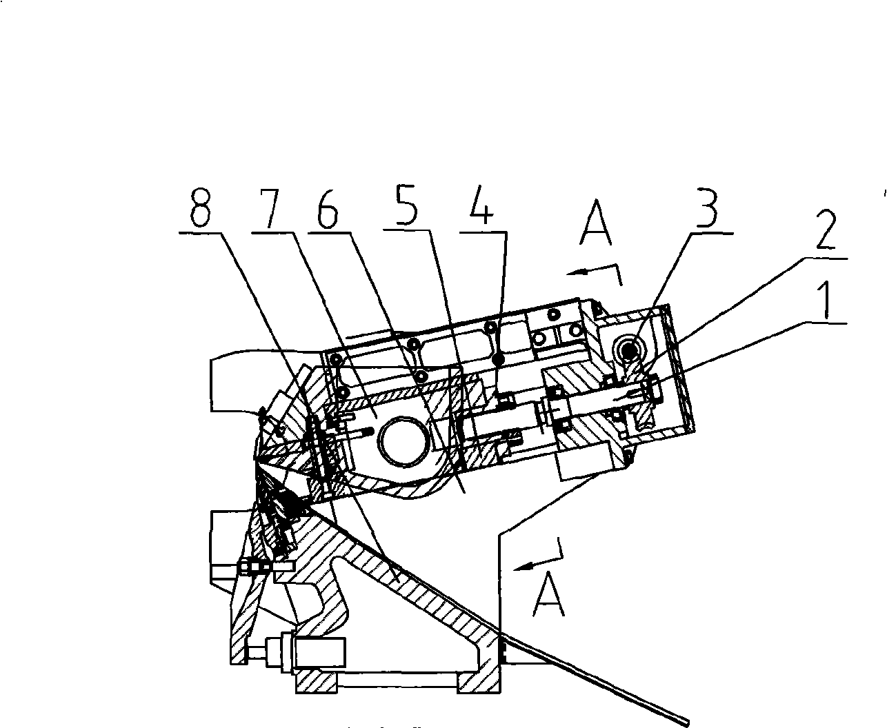
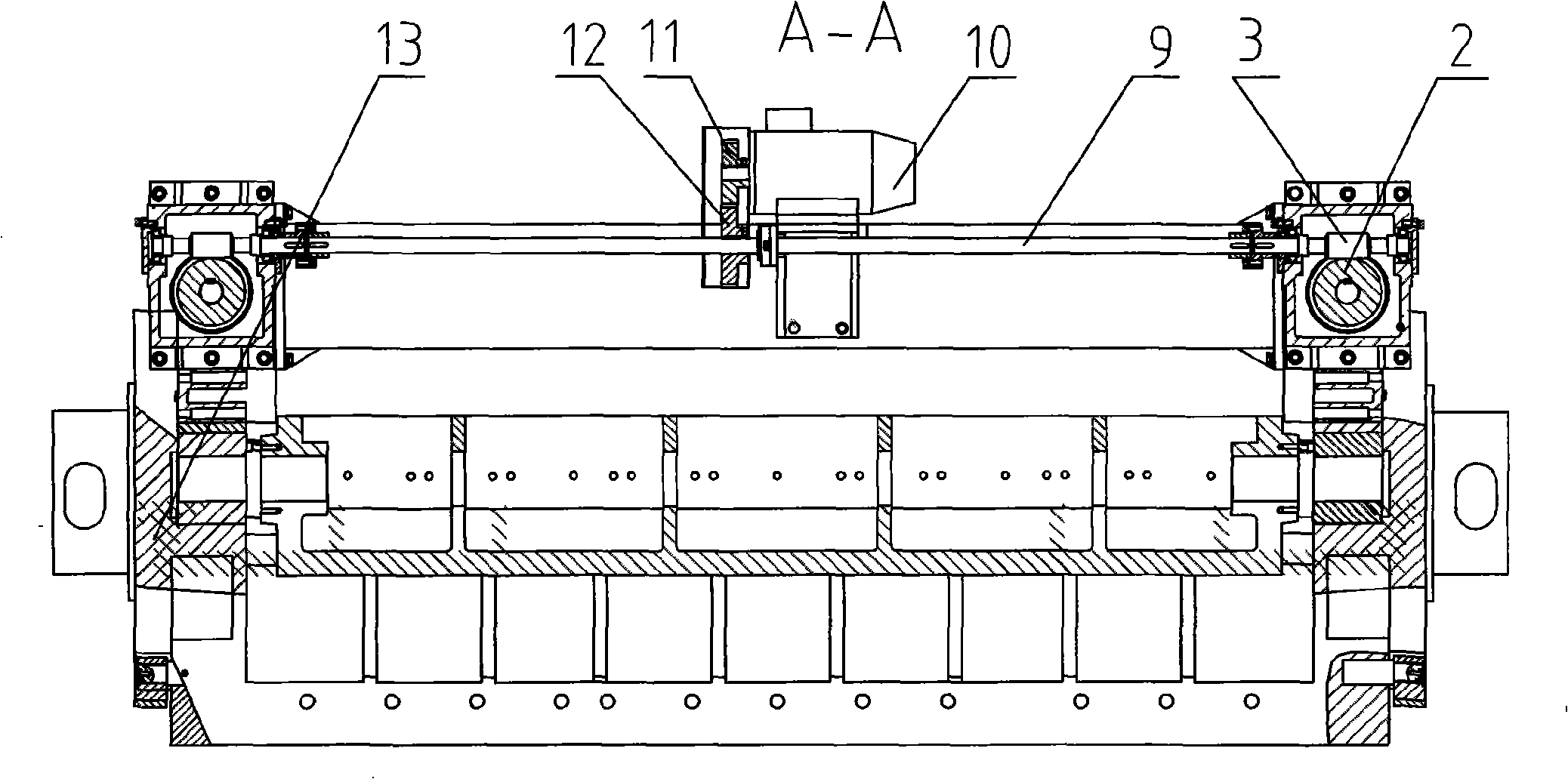
[0010] As shown in the figure, the knife door adjustment device of the CNC hydraulic double card shaft rotary cutter has a knife rest body 8 on the body 13, a guide rail 6 on the top of the knife rest body 8, a slide seat 5 on the guide rail 6, and a slide seat 5 on the guide rail 6. A pressure ruler frame 7 is provided on the top, and a servo motor 10 is provided on the body 13, and the servo motor 10 is connected with a leading screw 1, and the leading screw 1 is provided with a nut 4, and the nut 4 is connected with the sliding seat 5. As can be seen from the figure, the servo motor 10 is provided with a driving wheel 11, and one side of the servo motor 10 is provided with a transmission shaft 9, and the transmission shaft 9 is provided with a driven wheel 12, and the driving wheel 11 is meshed with the driven wheel 12, and the transmission shaft 9 one end is provided with worm screw 3, and worm screw 3 is provided with turbine 2, and turbine 2 is connected with lead screw 1...


PUM


Abstract

The invention discloses a device for adjusting the cutter of a numerical control hydraulic double-spindle veneer lathe, which relates to woodworking machinery. A cutter frame body is arranged on a machine body, a guide rail is arranged above the cutter frame body, a sliding seat is arranged on the guide rail, and a pressure bar frame is arranged on the sliding seat; a servo motor is arranged on the machine body and is connected with a leading screw; nuts are arranged on the leading screw, and the nuts are connected with the sliding seat. As the guide rail is arranged above the cutter frame body, the sliding seat is arranged on the guide rail, the pressure bar frame is arranged on the sliding seat, the servo motor is arranged on the machine body, the servo motor is connected with the leading screw, the nuts are arranged on the leading screw, and the nuts are connected with the sliding seat, the cutter can be adjusted in the operating state of the veneer lathe. When the thickness of a rotary veneer is changed, the servo motor is driven to adjust the cutter without shutting the machine down. The device has the advantages of simple operation, high adjusting precision and high working efficiency, and is suitable for adjusting the cutter of the numerical control hydraulic double-spindle veneer lathe.

Description

Technical field: [0001] The invention relates to woodworking machinery, in particular to a knife door adjusting device for a numerically controlled hydraulic double clamping shaft rotary cutter. Background technique: [0002] As we know, the existing CNC hydraulic double clamp shaft rotary cutting machine knife door adjustment device is that a knife rest body is arranged on the body, a pressure ruler frame is arranged above the knife rest body, a rotating shaft is arranged on the pressure ruler frame, and a rotating shaft is arranged on the rotating shaft. The eccentric mechanism, the eccentric mechanism rotates, drives the rotating shaft to rotate, and drives the pressure ruler frame to move and adjust the knife door. This kind of CNC hydraulic double-clamp rotary cutter knife door adjustment device cannot adjust the knife door in the working state. Every time the thickness of the rotary-cut veneer changes, it is necessary to turn off the CNC hydraulic double-clamp rotary c...

Claims


Application Information

Patent Timeline
IPC IPC(8): B27L5/02
Inventor 宋修财邵光智王成瑞王术进徐伟李洪娟邹希洪
Owner SHANDONG BAISHENGYUAN GRP
Why Eureka
Eureka Blog
Learn More