Electric blowing fan and electric vacuum cleaner equipped therewith

A blower, motor technology, applied in the direction of vacuum cleaners, mechanical equipment, machines/engines, etc., can solve the problems of inability to maintain the fan cover in the specified position, difficult to obtain the outer dimensional accuracy, damage to the diffuser or tailstock, etc., to achieve reliable diameter. Directional positioning, increased contact area, and improved operability

Active Publication Date: 2009-01-21
HITACHI APPLIANCES INC
View PDF1 Cites 7 Cited by
  • Summary
  • Abstract
  • Description
  • Claims
  • Application Information

AI Technical Summary

Problems solved by technology

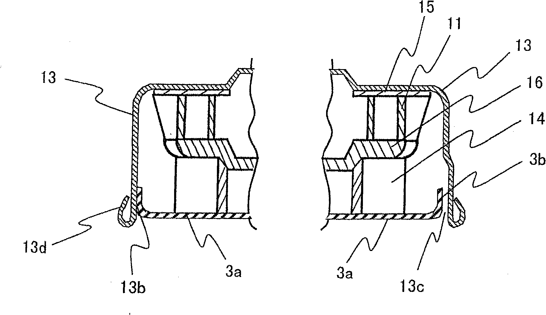
[0009] However, since the diffuser is molded from synthetic resin, it is difficult to obtain the dimensional accuracy of the outer circumference. Furthermore, since the tail bracket and the screws of the sheet metal processed product are used to fix it, it is difficult to obtain the same degree of accuracy between the outer circumference of the tail bracket pressed into the fan cover and the outer circumference of the diffuser. axis
Therefore, there is a danger of damaging the diffuser or the tailstock when pressing the fan cover, and there is a problem that the fan cover cannot be maintained at a predetermined position.

Method used


Image

  • Electric blowing fan and electric vacuum cleaner equipped therewith
  • Electric blowing fan and electric vacuum cleaner equipped therewith
  • Electric blowing fan and electric vacuum cleaner equipped therewith

Examples


Embodiment Construction

[0030] Embodiments of the present invention will be described below with reference to the drawings.

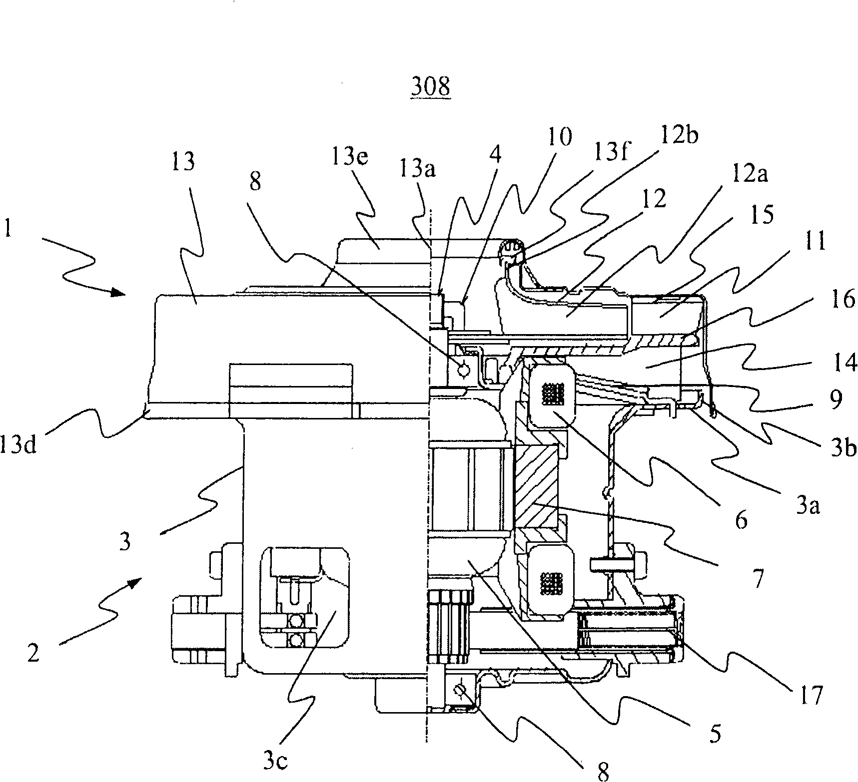
[0031] according to Figure 6 as well as Figure 7 An electric vacuum cleaner according to an embodiment of the present invention will be described. Figure 6 A perspective view showing the appearance of the electric vacuum cleaner of this embodiment.

[0032] Symbol 201 is to accommodate the dust collecting chamber for collecting dust and the electric blower 308 ( Figure 7 ), the symbol 202 is a hose connected to the vacuum cleaner body 201 at one end, the symbol 203 is the handle operation part connected to the other end of the hose 202, and the symbol 204 is an extension connected to the other end of the handle operation part 203 The pipe, symbol 205 is a suction body connected to the other end of the extension pipe 204 . Reference numeral 206 denotes a switch portion provided on the handle operating portion 203 for turning on and off the electric blower 308 .

[0033...


PUM


Abstract

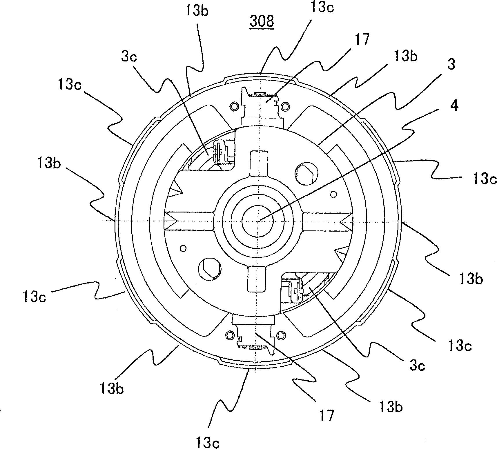
The invention relates to an electrical blower and an electric dust collector equipped with it. The invention aims to solve the problem that: the shell is distorted while the fan casing is pressed into; and the fan casing can not be kept on the set position, and the eccentricity and inclined installation of the fan casing can reduce the efficiency of the electrical blower. The electrical blower in the invention comprises: a shell for containing the motor, a fan casing installed on the shell covering the centrifugal fan and the diffuser; an extruding part is formed on the opening edge of one end of the shell; a fan casing installing component disposed from the extruding part to the centrifugal fan side or its opposite side; and an installing part contacting with the installing component and a non-installing part not connecting with the installing component are disposed on the inner surface of the fan casing.

Description

technical field [0001] The present invention relates to an electric blower and an electric vacuum cleaner equipped with it. Background technique [0002] In an existing electric blower for an electric vacuum cleaner, a diffuser is arranged between a centrifugal fan installed on a rotor shaft protruding from the motor housing and an air passage in the motor housing, and the diffuser and the fan motor housing are covered and the motor is covered. The fan cover is attached to the outer peripheral protrusion of the one-end opening edge of the housing. [0003] The edge portion of one end opening of the motor housing on which the fan cover is installed includes: an annular plane portion integrally protruding outward from the opening edge of one end of the housing main body; the front end of the plane portion is bent parallel to the main body to the opposite side of the fan and an outer peripheral protrusion bent outward from the front end of the cylindrical portion, and notches ...

Claims


Application Information

Patent Timeline
Patent Type & Authority Applications(China)
IPC IPC(8): F04D29/44F04D29/62A47L5/22A47L5/12
Inventor 坂上诚二常乐文夫杉村和之大平房德西冈嘉之本多武史
Owner HITACHI APPLIANCES INC
Why Eureka
Try Eureka