Packaging method and system of electric component

A technology of electrical components and installation methods, which is applied in the direction of electrical components, electrical components, electrical components, assembled printed circuits, etc., can solve problems such as low connection reliability, inability to fully ensure initial conduction resistance, insufficient heating connection reliability, etc. To achieve the effect of preventing voids

Active Publication Date: 2009-01-21
DEXERIALS CORP
View PDF2 Cites 2 Cited by
  • Summary
  • Abstract
  • Description
  • Claims
  • Application Information

AI Technical Summary

Problems solved by technology

[0008] In the case of the method of pressurizing and heating using such a crimping head such as a metal, there is also the following problem: when thermocompression bonding is performed, the swelling part of the adhesive around the IC chip is not heated enough to cause a connection problem. Reliability is low, and mounting of multiple IC chips is also difficult
[0012] However, in such prior art, there is a problem that sufficient connection cannot be made due to insufficient pressure between the bump portion and the pattern as the connection portion between the IC chip and the substrate, and the initial on-resistance cannot be sufficiently ensured. and connection reliability after aging

Method used


Image

  • Packaging method and system of electric component
  • Packaging method and system of electric component
  • Packaging method and system of electric component

Examples


Embodiment 1

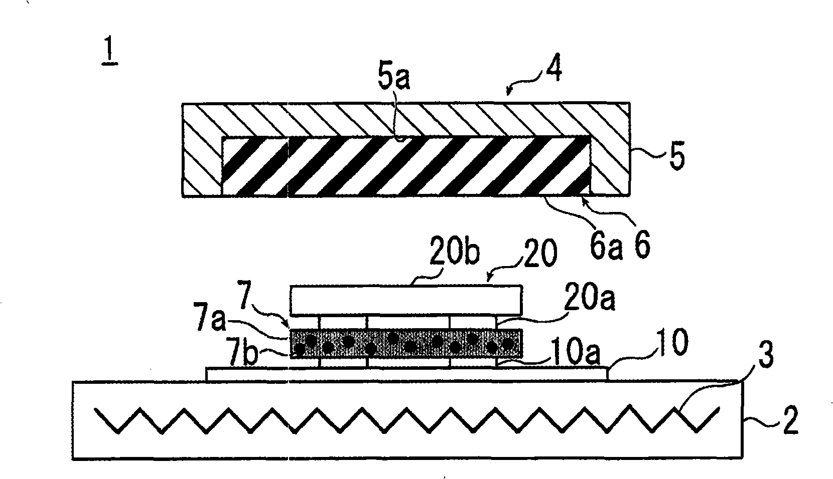
[0087] As the wiring substrate, a copper (Cu) pattern with a width of 75 μm and a pitch of 150 μm is formed on a glass fiber reinforced plastic substrate, and a rigid substrate plated with nickel and gold is used on it. As an IC chip, a size with bump electrodes with a pitch of 150 μm is prepared. 6×6mm, 0.4mm thick chip.

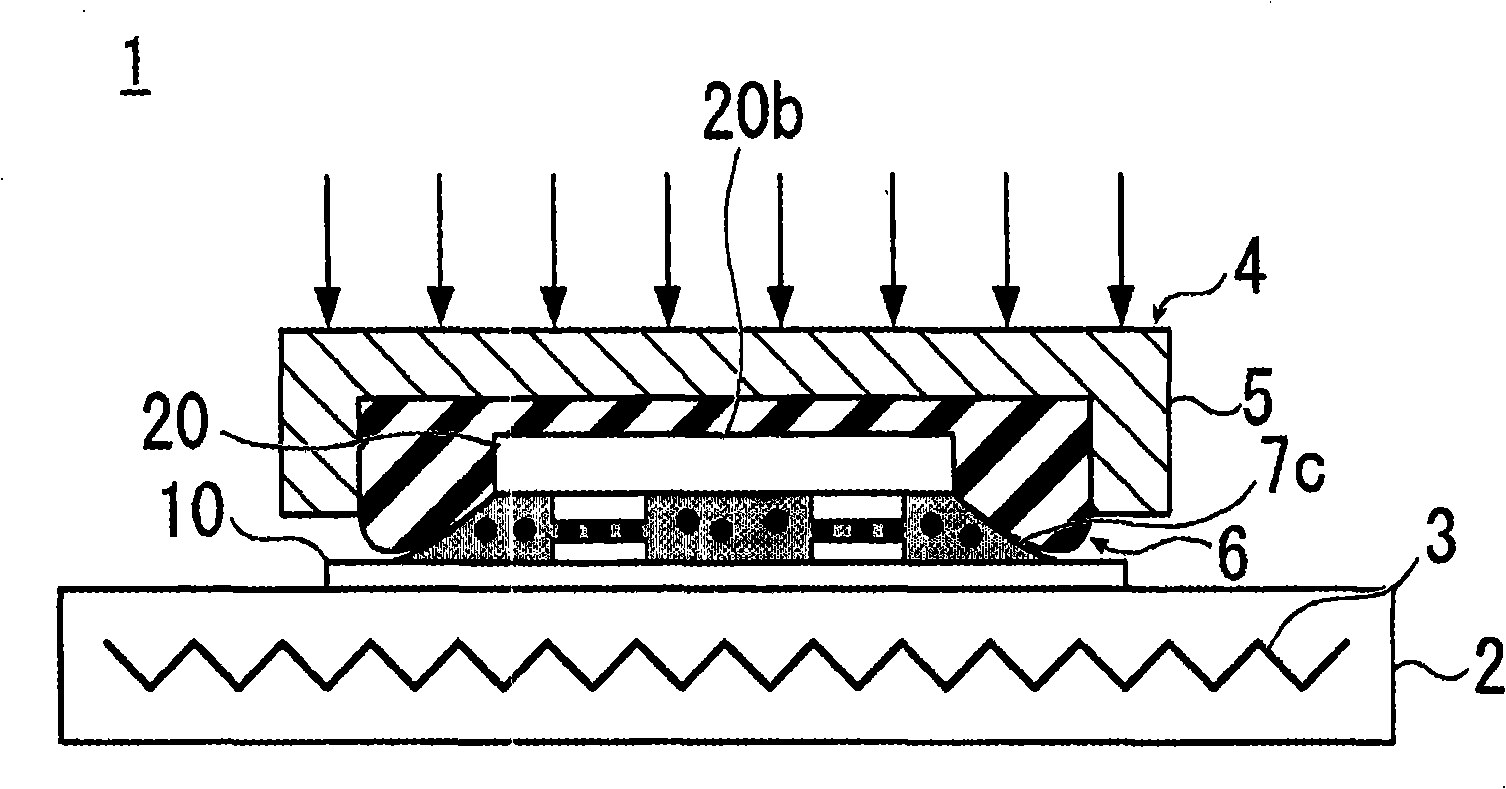
[0088] In addition, a thermocompression joint equipped with a crimping part made of silicone rubber with a size of 60×60mm, a thickness of 10mm, and a rubber hardness of 40 is used as an anisotropic conductive adhesive film with a melting viscosity of 1.0×10 5 A film in which conductive particles are dispersed in an adhesive resin of mPa·s to heat and compress the IC chip onto the wiring board.

[0089] In this case, control the temperature of the susceptor so that the temperature of the crimping part is 100℃, the temperature of the anisotropic conductive adhesive film is 200℃3, and the pressure is 100N / IC (278N / cm 2 ) Pressurize and heat within 15 seconds.

Embodiment 2

[0091] The thermocompression bonding was performed under the same conditions as in Example 1, except that a crimping portion made of silicone rubber with a rubber hardness of 80 was used.

Embodiment 3

[0097] Except when the melt viscosity is 1.0×10 2 Except for the anisotropic conductive adhesive film in which conductive particles are dispersed in the adhesive resin of mPa·s, thermocompression bonding was performed under the same conditions as in Example 1.


PUM


Abstract

A packaging method and a packaging system capable of packaging a high-reliability electric component using adhesive. The packaging method comprises a step for thermocompressing an IC chip (20) onto a wiring board (10) using an anisotropic conductive adhesive film (7), wherein the top region of the IC chip (20) is pressed against the wiring board (10) with a specified pressure at the time of thermocompression, and the side region of the IC chip (20) is pressed with a pressure lower than that for the top region of the IC chip (20). Elastomer having rubber hardness of 40-80 is employed as the compressing part (6) of a thermocompression head (4). The anisotropic conductive adhesive film (7) contains bonding resin (7b) having a melt viscosity of 1.0x10<2> to 1.0x10<5> mPa.s.

Description

[0001] This application is a divisional application of the following applications: [0002] Title of Invention: Installation method and installation device of electrical components [0003] International filing date: July 8, 2004 [0004] National application number: 200480019837.5 Technical field [0005] The present invention relates to a technique for mounting electrical components such as semiconductor chips on a wiring board, and particularly to a technique for mounting electrical components using adhesives. Background technique [0006] Conventionally, as a method of directly mounting a bare chip on a wiring board such as a printed circuit board, a method of using an anisotropic conductive adhesive film in which conductive particles are dispersed in an adhesive is known. [0007] In the mounting method using the anisotropic conductive adhesive film, the IC chip is mounted on the substrate with the anisotropic conductive adhesive film, and then the IC chip is pressurized with...

Claims


Application Information

Patent Timeline
Patent Type & Authority Applications(China)
IPC IPC(8): H01L21/60H05K3/32
CPCH01L2224/75252H01L2224/83855H01L24/83H01L2924/0781H01L2924/01002H01L24/29H01L2224/2929H01L2224/83101H01L2224/32225H05K3/323H01L2224/16H01L2924/01015H01L2924/00013H01L2224/16225H01L2924/01004H01L2924/01006H01L2924/01078H01L2924/01079H01L2224/29298H01L2924/14H01L2924/01005H01L2224/29299H01L2224/73204H01L2224/2919H01L2224/75251H01L2924/014H01L2924/07811H01L2924/01029B30B5/02B30B15/065H01L2924/01033H01L2924/0665H01L2224/75315H01L24/75H01L2224/7598H01L2924/00H01L2924/00014H01L2224/29099H01L2224/29199H05K13/04H05K3/32
Inventor 松村孝安藤尚蟹泽士行须贺保博工藤宪明
Owner DEXERIALS CORP
Why Eureka
Try Eureka