
Method for configuring main change reactive compensation capacitor set of transformer substation

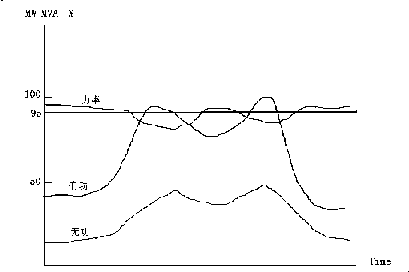
A technology for compensating capacitors and configuration methods, applied in reactive power compensation, reactive power adjustment/elimination/compensation, etc., can solve the problem of inability to maintain voltage network loss, inability to effectively perform reactive power compensation, and unreasonable capacitor grouping configuration and other problems, to achieve the effect of avoiding equipment investment waste, reducing the impact of faults, and reducing line energy loss.

Inactive Publication Date: 2009-01-21
田田
View PDF0 Cites 13 Cited by
  • Summary
  • Abstract
  • Description
  • Claims
  • Application Information

AI Technical Summary

Problems solved by technology

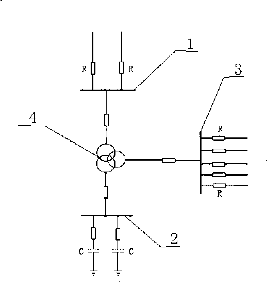
[0012] In order to overcome the deficiencies in the prior art, the present invention provides a method for configuring groups of reactive power compensation capacitors for substation main transformers. It is necessary to solve the problem of unreasonable configuration of capacitor groups and the inability to effectively perform reactive power compensation, resulting in waste of equipment and failure to maintain voltage, Technical Problems of Reducing Network Loss

Method used


Image

  • Method for configuring main change reactive compensation capacitor set of transformer substation
  • Method for configuring main change reactive compensation capacitor set of transformer substation
  • Method for configuring main change reactive compensation capacitor set of transformer substation

Examples


Embodiment

[0057] Example: In a substation, there are two main transformers in total, and each main transformer needs reactive power compensation of 20000Kvar. According to the design of 4 sets of capacitors for each main transformer, the configuration of capacitors should be calculated as follows:

[0058] Since there are 4 sets of capacitors for each main transformer, then take the four coefficients corresponding to the 4 sets of capacitors in Table 2:

[0059] 0.143

0.214

0.286

0.357

[0060] Since each main transformer needs reactive power compensation of 20000Kvar, the capacity of each group of capacitors of the main transformer is the total compensation amount multiplied by their respective coefficients, namely:

[0061] The capacity of the first group of capacitors = 20000x0.143 = 2860Kvar

[0062] The capacity of the second group of capacitors = 20000x0.214 = 4280Kvar

[0063] The capacity of the third group of capacitors = 20000x0.286 = 5720Kvar

...


PUM


Abstract

The present invention provides a configuration method of main reactive compensation capacitor group of transformer substation. The configuration method is characterized by the following steps: first, arranging the capacitance ratio of capacitors according to the optimum capacitance ratio of the capacitors; secondly, the reactive compensation capacitance required by the main transformer of the transformer substation is directly multiplied by the corresponding coefficient in Table 2, to acquire the capacitance of the group of capacitors. The formula of optimum indexes in Formula I is adopted to optimize the configuration of the main reactive compensation capacitor group of transformer substation. The configuration method solves the technical problem that the improper configuration of the main reactive compensation capacitor group of transformer substation can not effectively complete the reaction compensation, leads to the equipment waste, and has no function of maintaining the voltage and reducing the net loss.

Description

technical field [0001] The invention relates to a method for configuring and combining capacitor capacities of substations in electric power systems, in particular to a method for configuring and combining reactive power compensation capacitors for main transformers in substations. Background technique [0002] As the power supply load is getting heavier, the problem of reactive power compensation of the main transformer in the substation is becoming more and more important. However, how to optimize the grouping of reactive power compensation capacitors in the construction and transformation of the power grid to achieve better operating results is lacking in theory and methods. , in actual work, the allocation of capacitor capacity is unreasonable and often does not play its due role. [0003] The daily use is alternating current, alternating current includes active components and reactive components, it is the active components that make the watt-hour meter run, and the rea...

Claims


Application Information

Patent Timeline
IPC IPC(8): H02J3/18
CPCY02E40/30
Inventor 田田谢雄威刘海燕陈兆猛田业尤承佳黄坚
Owner 田田
Learn More