Apparatus and method for compensating polarization membrane dispersion in network for forming light control microwave beam

A polarization mode dispersion, microwave beam technology, applied in the field of optical communication

Inactive Publication Date: 2009-01-21
TSINGHUA UNIV
View PDF0 Cites 12 Cited by
  • Summary
  • Abstract
  • Description
  • Claims
  • Application Information

AI Technical Summary

Problems solved by technology

However, there are few reports on compensating PM

Method used


Image

  • Apparatus and method for compensating polarization membrane dispersion in network for forming light control microwave beam
  • Apparatus and method for compensating polarization membrane dispersion in network for forming light control microwave beam
  • Apparatus and method for compensating polarization membrane dispersion in network for forming light control microwave beam

Examples


Embodiment Construction

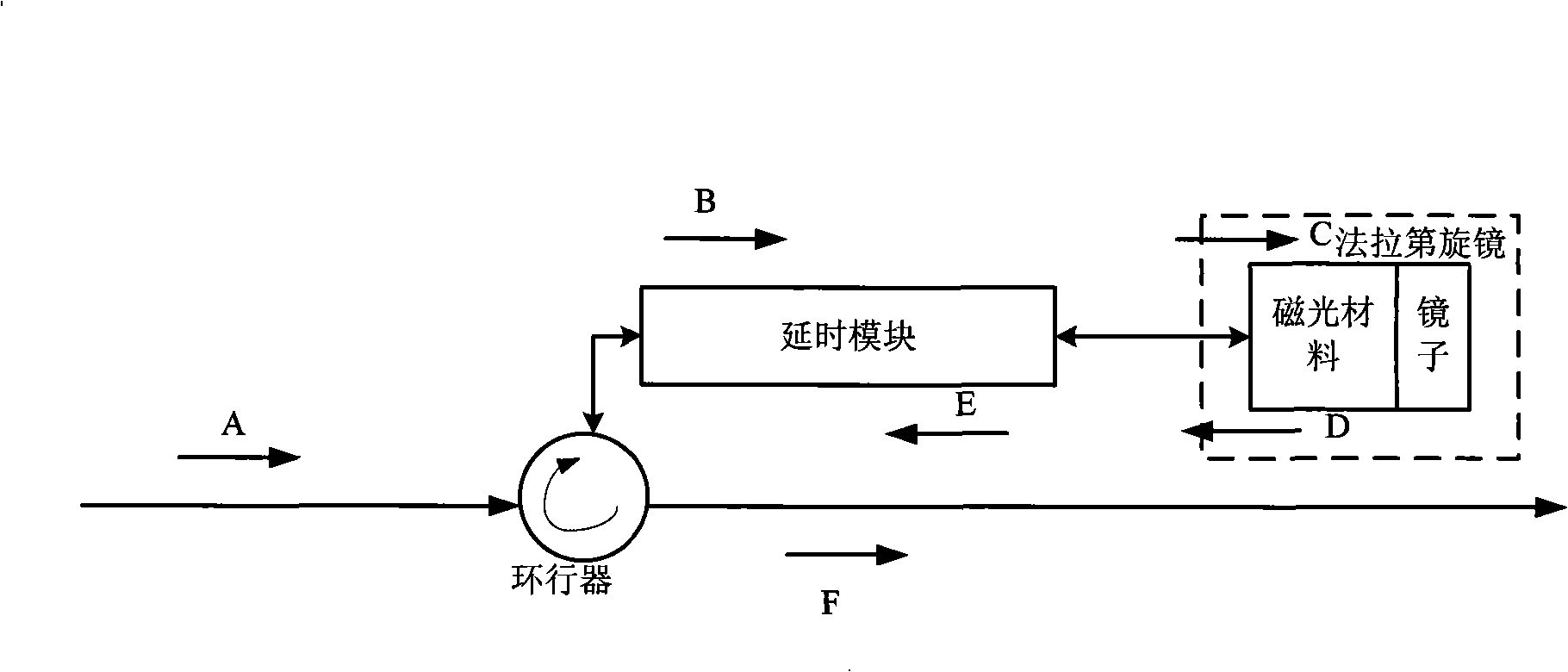
[0030] The present invention provides an experimental device for compensating the polarization mode dispersion of the delay module in the optical control beam forming network by using the Faraday rotation mirror, including a 90-degree Faraday rotation mirror and a circulator, such as figure 1 , as shown in:

[0031] The polarization mode compensation of the optical beamforming network delay module uses a 90-degree Faraday rotating mirror;

[0032] The circulator connects the optical delay module and the optical link, and the reflection of the circulator and the Faraday rotation mirror realizes the reverse propagation of the light.

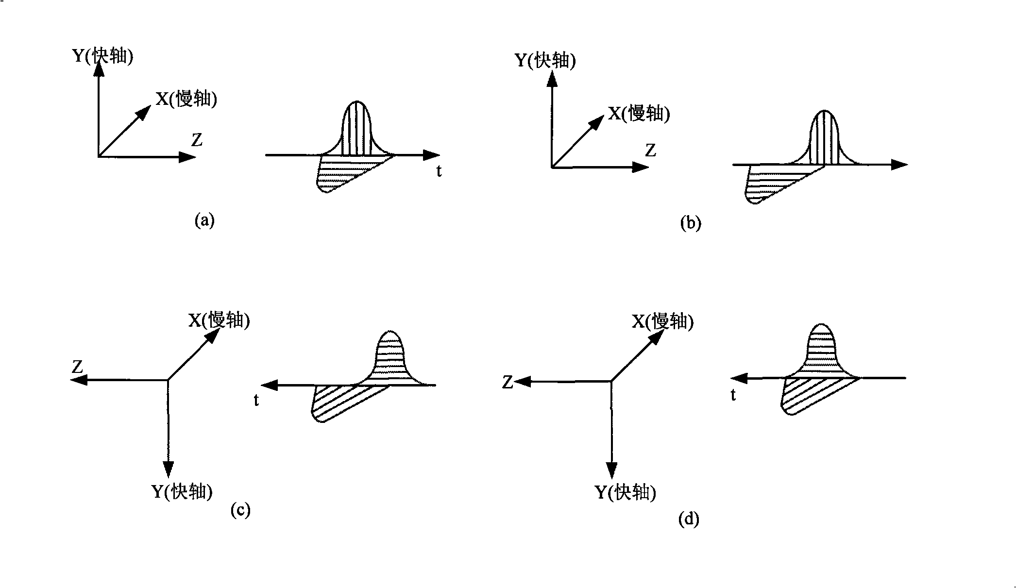
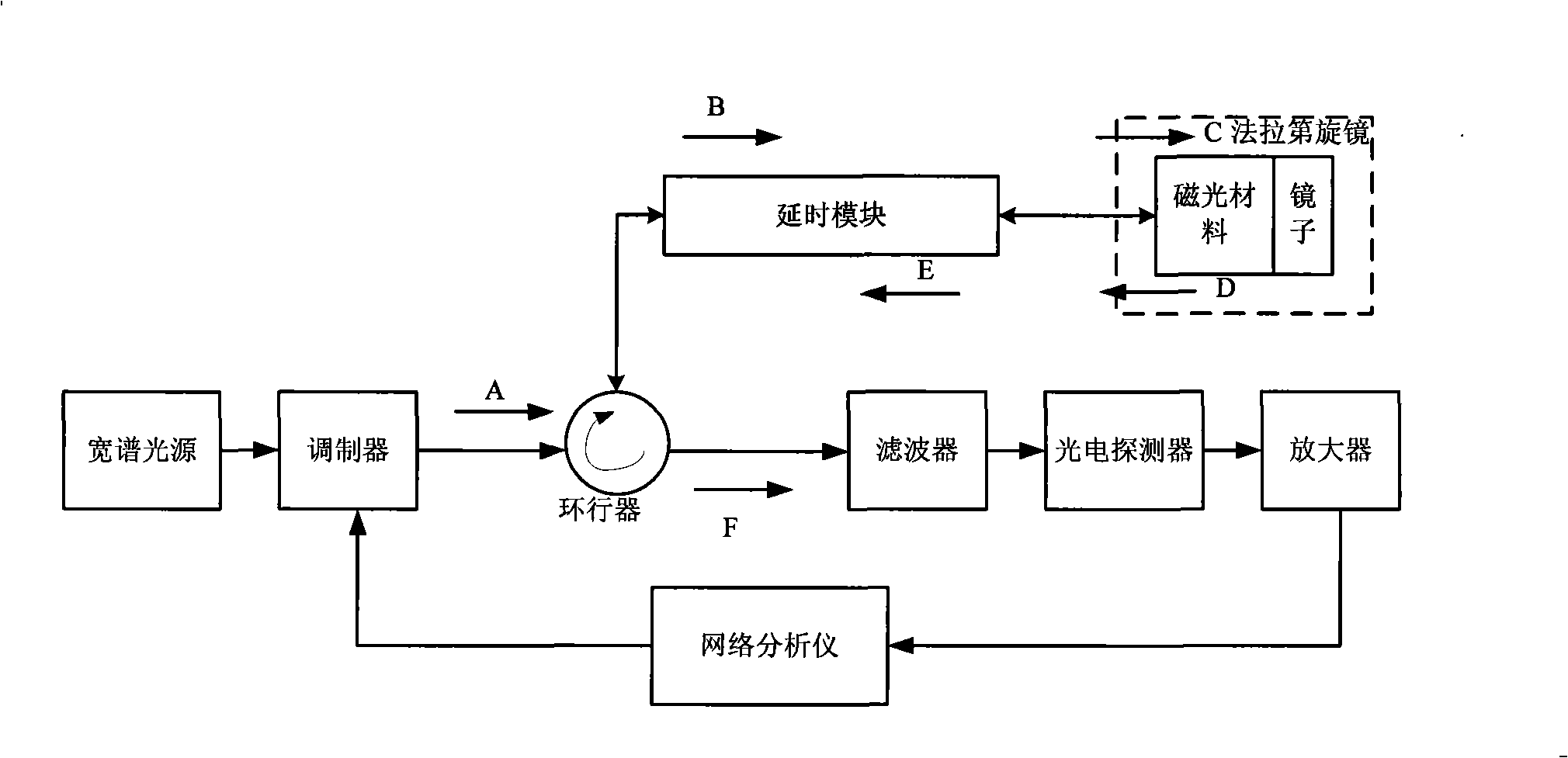
[0033] The present invention provides a method for compensating the polarization mode dispersion of the delay module in the optical control beam forming network by using the Faraday rotation mirror, such as figure 2 , 3 , as shown, includes the following steps:

[0034] The input light modulated by the signal enters the delay module through th...


PUM


Abstract

The present invention relates to a compensation device of polarization module dispersion in the optically controlled microwave beam forming network, and a method thereof, belonging to the technical field of compensation of the polarization module dispersion. The compensation device is characterized by comprising a circulator, a delay module, and a 90-degree Faraday rotating mirror; the circulator is used for transmitting the input light of modulated signals; the delay module adopts the principle of Jones matrix to polarize the input light of the circulator so as to realize the delay with the influence of polarization module dispersion; the 90-degree Faraday rotating mirror adopts the Jones matrix to transform the signal light transmitted from the delay module into a reflective electric field; the signal light is transmitted reversely to realize the compensation of the polarization module dispersion, and is transmitted outwards by an analyzer after entering an optical link, so as to compensate the corresponding polarization module dispersion. The compensation device has the advantages of simple structure and low costs.

Description

technical field [0001] The invention belongs to the technical field of optical communication, and particularly relates to polarization mode dispersion compensation, system polarization stability, delay accuracy and delay adjustment of an optical true delay module in a microwave beam forming network system. Background technique [0002] Optically controlled microwave beamforming networks are an important application of microwave photonics. It is a beamforming network that uses light waves to control microwaves, that is, uses the characteristics of optical devices and light wave transmission to perform power distribution and phase control on microwave signals, thereby realizing the control and scanning of the spatial distribution of microwave signals. The key module of the optically controlled microwave beamforming network is the optical real delay network. The optically controlled microwave beamforming network with optical true delay technology as the core has broad applicat...

Claims


Application Information

Patent Timeline
IPC IPC(8): H04B10/18H04B10/2525
Inventor 郑小平李遥宋怡桥周炳琨
Owner TSINGHUA UNIV
Why Eureka
Try Eureka