Surface mounting type power inductor

A surface mount, power inductor technology, applied in inductors, fixed inductors, transformer/inductor cores, etc., to solve problems such as shortening the total length of the coil, reducing the inductance L, and reducing the DC resistance.

Inactive Publication Date: 2009-01-21
TODA ISU
View PDF0 Cites 11 Cited by
  • Summary
  • Abstract
  • Description
  • Claims
  • Application Information

AI Technical Summary

Problems solved by technology

Therefore, the overall length of the coil is shortened, resulting in a decrease in DC resistance
However, due to this, the inductance L is reduced under high current conditions

Method used


Image

  • Surface mounting type power inductor
  • Surface mounting type power inductor
  • Surface mounting type power inductor

Examples


Embodiment Construction

[0019] Hereinafter, preferred embodiments of the present invention will be described in detail with reference to the accompanying drawings. In the following description, some explanations of conventional functions or conventional structures may be considered unnecessary if they prevent the understanding of the gist of the present invention.

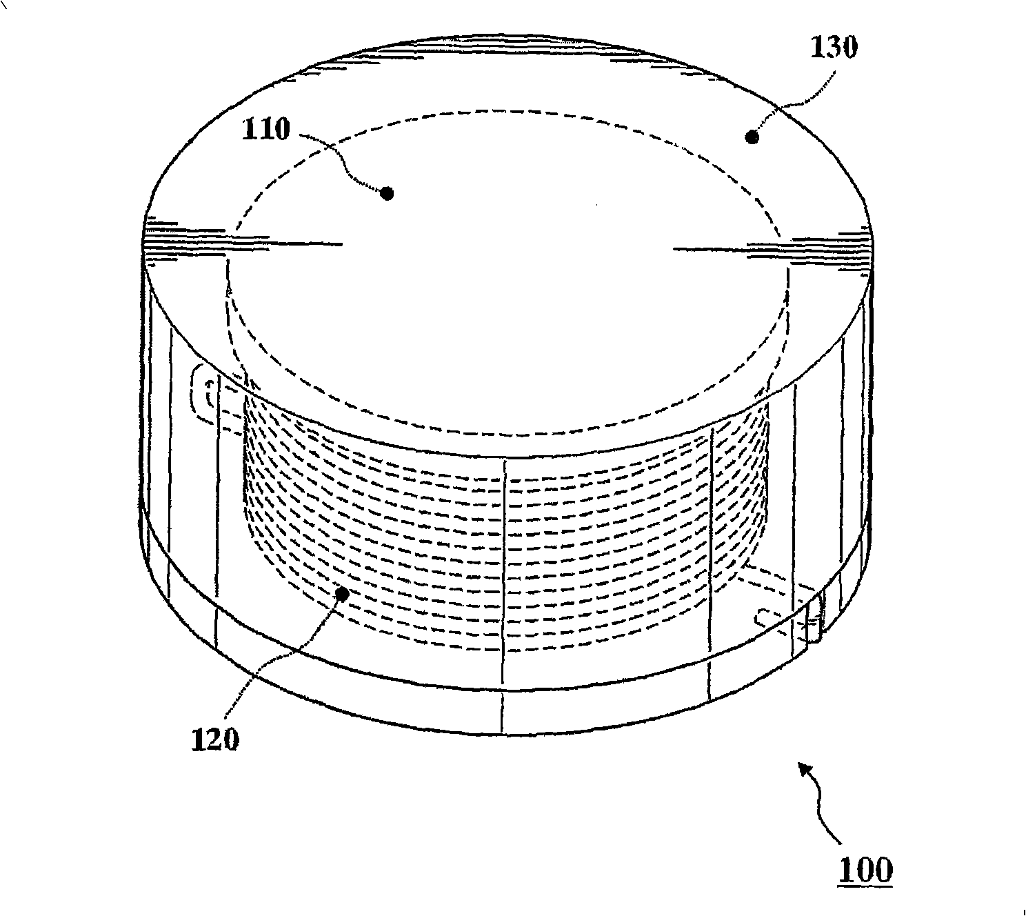
[0020] refer to figure 2 , shows a surface mount type power inductor (hereinafter referred to as "inductor") 100 according to the present invention. Such as figure 2 As shown, the inductor 100 includes an inner core 110, a coil 120 wound on the inner core with a predetermined number of turns, and an outer magnetic envelope 130 covering the inner core wound with the coil.

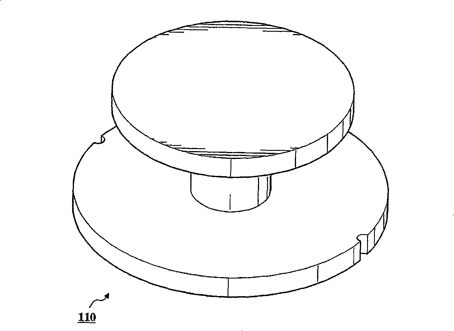
[0021] The inner core 110, made of ferrite or magnetic metal, can be formed as Figure 3a The circular drum shown, Figure 3b The shown square drum shape, T-shape (not shown) or I-shape (not shown).

[0022] Such as Figure 4a and 4b As shown, the coil 120 is w...


PUM

PropertyMeasurementUnit
diameteraaaaaaaaaa
electrical resistanceaaaaaaaaaa

Abstract

Disclosed herein is a surface mount type power inductor which has an outer magnetic capsule integrated with a coil-wound inner core, and which thus has no air gap between the outer magnetic capsule and the inner core, and can maintain a large inductance L in a high current condition. In the inductor, a coil is wound a predetermined number of turns around the inner core formed from ferrite or magnetic metal. An outer magnetic capsule, molded from a magnetic powder, an insulation filler, a binder, and a lubricant, is provided to cover the inner core and the coil.

Description

technical field [0001] The present invention relates to surface mount type power inductors. Background technique [0002] With the focus on the development of various electronic devices towards slimness and high performance, the power circuit that provides power is also designed not only to meet the requirements of large capacity, but also to meet the requirements of slimness and shortness. In particular, since central processing units (CPUs) used in personal computers aim at large capacity and high speed, their power consumption is increasing day by day. In order to meet this demand, the power circuit is changed and adjusted to a switch regulation type instead of the traditional linear regulation type. [0003] Such as figure 1 As shown, the power inductor commonly used in power circuits has a double-core structure. The double-core structure is composed of an inner core 10 and an outer core 20 encapsulating the inner core. The inner core 10 is wound with a coil with a pre...

Claims


Application Information

Patent Timeline
Patent Type & Authority Applications(China)
IPC IPC(8): H01F27/24
CPCH01F2017/048H01F17/045H01F27/027H01F27/292H01F3/10H01F27/24H01F3/14
Inventor 宋炳武申载营李相卿
Owner TODA ISU
Why Eureka
Try Eureka