Molding wheel for drip irrigation belt

A technology of drip irrigation belt and forming wheel, which is applied to other household appliances, household appliances, applications, etc., can solve the problems of incompatibility of forming discs, complicated processing procedures, and high cost, and achieves reduction of processing costs, reduction of processing volume, and improvement of The effect of precision

Inactive Publication Date: 2009-01-28
XINJIANG TIANYE GRP
View PDF0 Cites 17 Cited by
  • Summary
  • Abstract
  • Description
  • Claims
  • Application Information

AI Technical Summary

Problems solved by technology

[0003] The purpose of the present invention is to provide an integral forming wheel, which solves the problem...

Method used


Image

  • Molding wheel for drip irrigation belt
  • Molding wheel for drip irrigation belt
  • Molding wheel for drip irrigation belt

Examples


Embodiment Construction

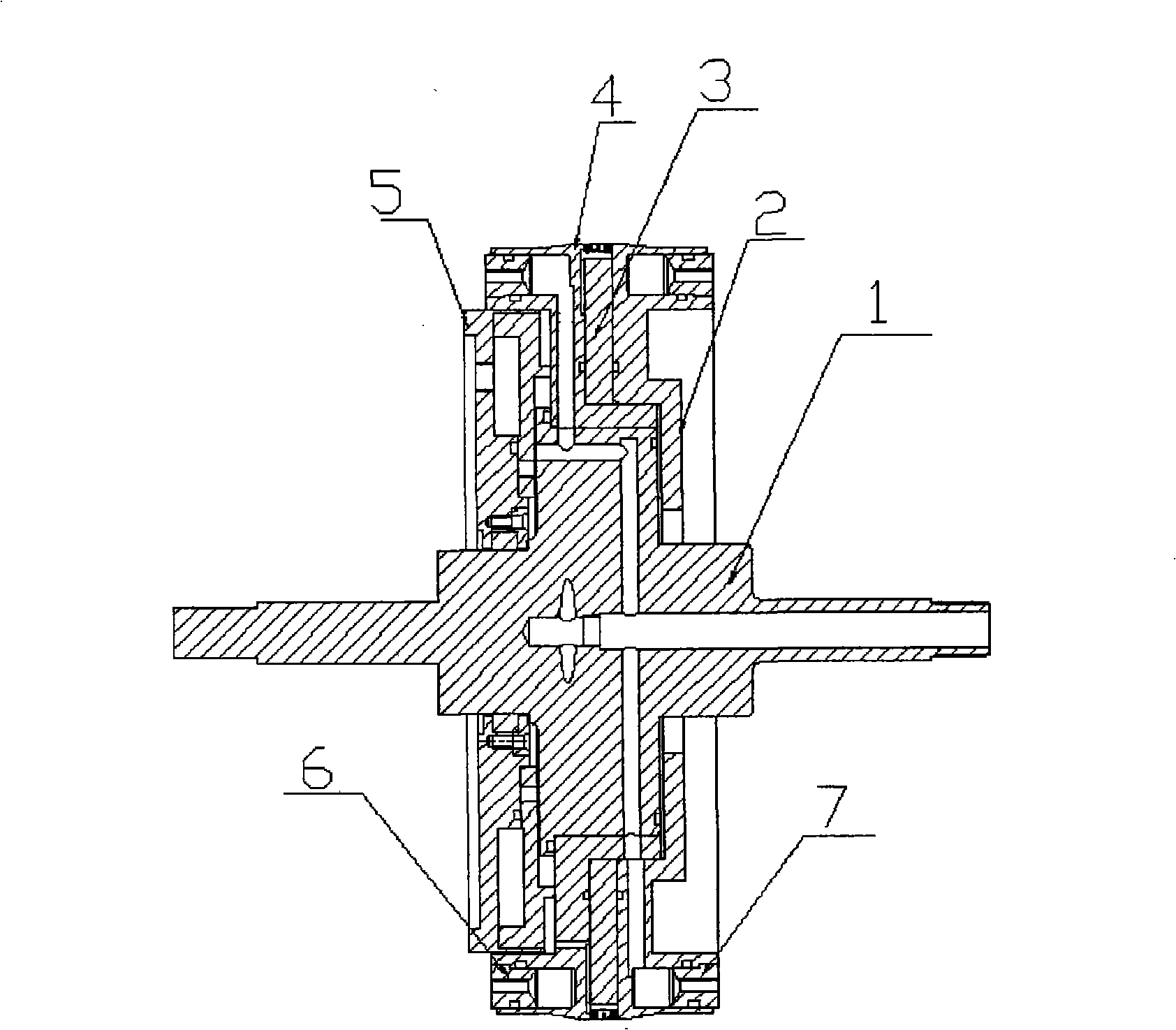
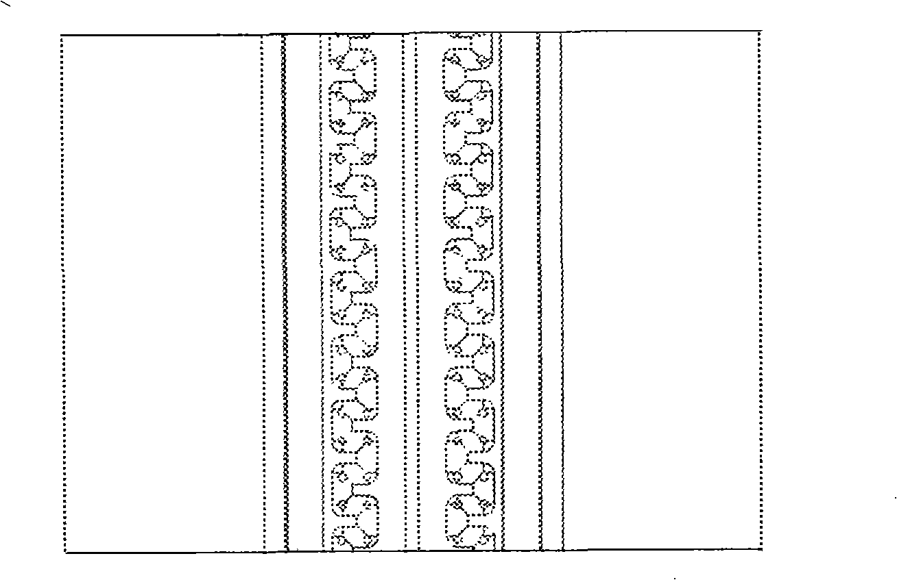
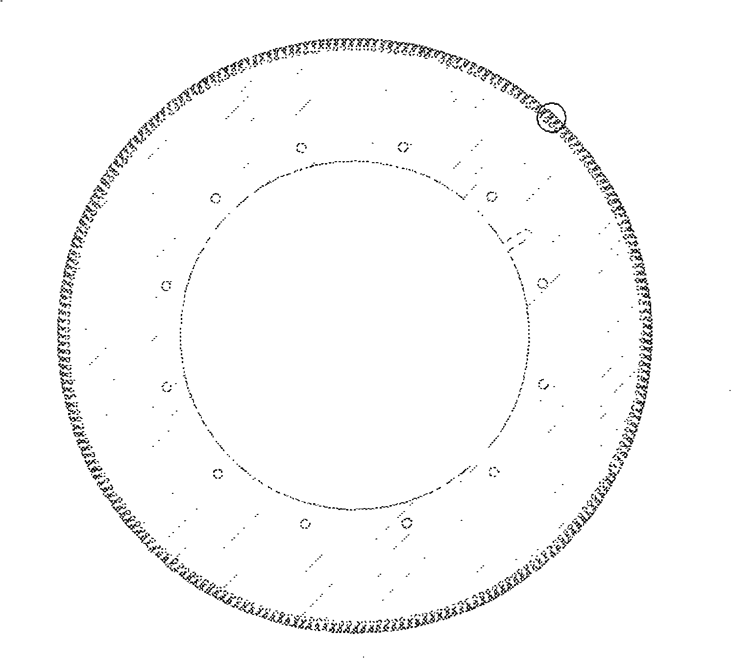
[0012] refer to Figures 1 to 4 , The forming wheel described in this embodiment is mainly composed of shaft 1, right cooling plate 2, forming plate 3, left cooling plate 4, vacuum cover 5, sealing water ring (left) 6, and sealing water ring (right) 7. Install the forming plate 3 on the left cooling plate 4 first, and then assemble it with the right cooling plate 2. The forming plate 3 is located in the middle of the left cooling plate 4 and the right cooling plate 2, at the position corresponding to the water channels of the left cooling plate 4 and the right cooling plate 2 Assemble the sealing water ring (left) 6 and the sealing water ring (right) 7. Then the shaft 1 is installed in the center of the left and right cooling discs, and the vacuum cover 5 is installed on the left end of the shaft. The end surface of the forming plate 3 is evenly distributed with small holes directly connected with the air groove of the left cooling plate 4, and a ring groove is arranged in th...


PUM


Abstract

The invention relates to a labyrinth drip irrigation tape forming wheel, consisting of a shaft, a left cooler pan, a right cooler pan, a forming pan, a water sealing ring and a vacuum pan; wherein, the end face of the forming pan is provided with a small hole which is communicated with an air drain of the left cooler pan, the middle of the outer round face of the forming pan is provided with a ring groove, labyrinth flow passages are symmetrically arranged at two sides of the ring groove, a corner of the labyrinth flow passage is provided with a micropore which is communicated with a small hole on the end face of the forming pan. The labyrinth drip irrigation tape forming wheel is characterized in that: the assembly accuracy of the forming wheel can be increased, the flow deviation of the produced drip irrigation tape can be reduced, the purpose that the drip irrigation tapes with different flow rates are produced by one set of wheels can be realized under the condition that only the forming pan is replaced; furthermore, the processing procedures of the forming pan are reduced, therefore, the cost is lowered.

Description

Technical field: [0001] The invention belongs to the technical field of agricultural water-saving irrigation equipment, and is particularly suitable for forming wheels used in the production of labyrinth drip irrigation belts. Background technique: [0002] The existing drip irrigation belt molding wheel is composed of a molding disk, left and right cooling disks, a septum ring, a shaft, a vacuum cover and a sealing water ring corresponding to the water channels of the left and right cooling disks. Among them, the forming plate is the core component of the labyrinth channel forming of the drip irrigation belt. It is composed of the left and right forming plates and the septum ring. The septum ring is installed in the middle of the left and right forming plates. The plate and the septum ring are provided with air holes at the positions corresponding to the air grooves of the left cooling plate, and the outer circular surfaces of the left and right forming plates are provided ...

Claims


Application Information

Patent Timeline
IPC IPC(8): B29C43/46B29C43/52B29L23/00
Inventor 李双全贾世疆朱财张守军马星才兰明王长林黄霞叶德海李振江李伟赵洪强刘耀海方锐栋丛健黄健
Owner XINJIANG TIANYE GRP
Why Eureka
Try Eureka