Water-cooled wall of 700 DEG C twice reheating horizontal side wall opposed firing boiler and working method

A secondary reheating and water-cooled wall technology, which is applied to boiler water pipes, combustion methods, lighting and heating equipment, etc., can solve the problems of increasing the reheating radiation heating surface, large flow area of ​​water-cooled wall, and increased heat absorption ratio. Achieve the effects of increasing the reheat radiation heating surface, reducing flow deviation, and suppressing local overheating

Pending Publication Date: 2019-04-12
XIAN THERMAL POWER RES INST CO LTD
View PDF0 Cites 0 Cited by
  • Summary
  • Abstract
  • Description
  • Claims
  • Application Information

AI Technical Summary

Problems solved by technology

This layout method firstly solves the problem of large flow area and low flow rate of the water-cooled wall of the 700°C double-reheated horizontal side wall confronting boiler; It is relatively close, which significantly reduces the problem of flow deviation of the water-cooled wall tubes, and effectively suppresses the problem of local overheating of the water-cooled wall; in addition, the arrangement of the primary reheating water cooling wall and the secondary reheating water cooling wall increases the reheat radiation heating surface , which effectively solves the problem that the heat absorption ratio of the first reheat and the second reheat of the 700°C double reheat boiler significantly increases, and at the same time avoids the problem of arranging the wall reheater for the horizontal side wall opposed boiler

Method used


Image

  • Water-cooled wall of 700 DEG C twice reheating horizontal side wall opposed firing boiler and working method

Examples


Embodiment Construction

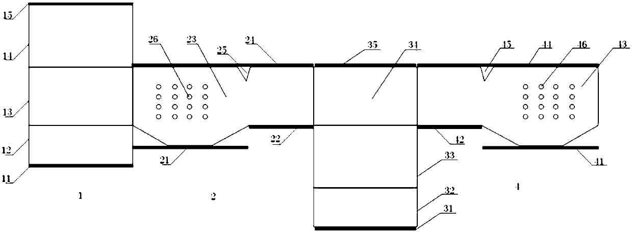
[0022] The present invention is described in further detail below in conjunction with accompanying drawing:

[0023] Such as figure 1 As shown, the water-cooled wall system of a 700°C double-reheated horizontal side wall counter-boiler in the present invention includes a front wall 1 , a right wall 2 , a rear wall 3 and a left wall 4 . Among them, the front wall 1 includes the front wall inlet header 11, the front wall primary reheating furnace bottom water cooling wall 12, the front wall primary reheating water cooling wall 13, the front wall primary reheating furnace top water cooling wall 14 and the front wall outlet header 15; the right wall 2 includes the first inlet header 21 of the right wall, the second inlet header 22 of the right wall, the water cooling wall 23 of the right wall, the outlet header 24 of the right wall, the flame angle 25 and The burner hole 26 in the right wall; the rear wall 3 includes the rear wall inlet header 31, the rear wall secondary reheatin...


PUM


Abstract

The invention discloses a water-cooled wall of a 700 DEG C twice reheating horizontal side wall opposed firing boiler and a working method. The water-cooled wall comprises a front wall, a right sidewall, a rear wall and a left side wall. By fully considering the parameter characteristics and the heat absorption distribution ratio of the 700 DEG C twice reheating boiler, perpendicular pipe ring membrane water-cooled walls are arranged on the right side wall and the left side wall, a perpendicular pipe ring once reheating membrane water-cooled wall is arranged on the front wall, and a perpendicular pipe ring twice reheating membrane water-cooled wall is arranged on the rear wall; firstly, the problems of large flow area and low flow rate of a water-cooled wall of a 700 DEG C twice reheating horizontal side wall opposed firing boiler are solved; secondly, the degree of the flow deviation of a water-cooled wall pipe is remarkably reduced, and the problem that the local over temperature of the water-cooled wall is effectively inhibited; in addition, the once reheating water-cooled wall and the twice reheating water-cooled wall are arranged, and the heating surface of the reheating radiation is increased; and the problem of the significant increase in the proportion of the heat absorption of once heating and twice heating of the 700 DEG C twice reheating boiler is effectively solved, and meanwhile, the difficult problem of arranging a wall reheating device on the horizontal side wall opposed firing boiler is avoided.

Description

technical field [0001] The invention belongs to the technical field of high-efficiency power generation, and specifically relates to a water-cooled wall and a working method of a 700°C double-reheated horizontal sidewall-hedging boiler. Background technique [0002] 700℃ ultra-supercritical power generation technology is one of the important technical directions for efficient power generation in the future. In order to pursue higher efficiency, the United States, Japan, and Europe have successively carried out research on ultra-supercritical 700°C power generation technology since the 1980s. Since the end of the 1990s, Europe, Japan, the United States, India and other countries and regions have successively launched 700 ℃ ultra-supercritical power generation technology research programs, such as the European AD-700 and subsequent series programs, and the USC program (Ultra- SupercriticalSteam Project), Japan's A-USC program, India's Adv-USC, etc. In 1998, Europe launched t...

Claims


Application Information

Patent Timeline
Patent Type & Authority Applications(China)
IPC IPC(8): F22B37/10F23M5/08
CPCF22B37/10F23M5/08
Inventor 张一帆李红智姚明宇白文刚杨玉
Owner XIAN THERMAL POWER RES INST CO LTD
Why Eureka
Try Eureka