Micro current detection circuit, micro current switching circuit

A detection circuit and switching circuit technology, applied in the direction of measuring current/voltage, changing the range circuit, measuring device, etc., can solve the problem that the reference voltage source cannot achieve mV level, can not achieve milliamp detection, etc.

Inactive Publication Date: 2012-02-22
王红艳
View PDF0 Cites 1 Cited by
  • Summary
  • Abstract
  • Description
  • Claims
  • Application Information

AI Technical Summary

Problems solved by technology

[0005] The defect of the existing technology is that, since the reference voltage source cannot achieve the mV level, the detected current is all at the ampere level, that is, the detection at the milliampere (mA) level cannot be achieved.

Method used


Image

  • Micro current detection circuit, micro current switching circuit
  • Micro current detection circuit, micro current switching circuit
  • Micro current detection circuit, micro current switching circuit

Examples


Embodiment Construction

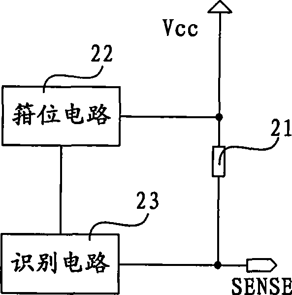
[0026] figure 2 It is a schematic diagram of an embodiment of the micro-current detection circuit of the present invention. The micro current detection circuit of this embodiment may include a sampling resistor 21 , a clamping circuit 22 and an identification circuit 23 . One end of the sampling resistance 21 is connected with the detection terminal SENSE of the identification circuit 23 and the detected circuit, and the other end of the sampling resistance 21 is connected with the power supply Vcc and the clamping circuit 22; the identification circuit 23 is connected with the clamping circuit 22 .

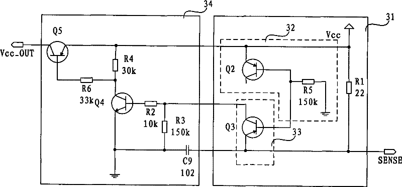
[0027] In this embodiment, both the clamping circuit 22 and the identification circuit 23 include triodes; the triodes in the identification circuit 23 and the clamping circuit 22 can be identical, and can be PNP transistors (Positive-Negative-Positive Transistor, PNP for short), or It is an NPN transistor (Negative-Positive-Negative Transistor, NPN for short). The clamping c...


PUM


Abstract

The invention relates to a microcurrent detection circuit and a microcurrent switch circuit. The microcurrent detection circuit comprises a sampling resistor, one end of the sampling resistor is connected with a detection end of a recognition circuit and a detected circuit, the other end of the sampling resistor is connected with power supply and a clamper circuit, the recognition circuit is connected with the clamper circuit; both the recognition circuit and the clamper circuit comprise a triode, the triodes in the recognition circuit and the clamper circuit have the same model, an emitter bias voltage of the triode in the clamper circuit equals to the supply voltage minus the clamper voltage, an emitter bias voltage of the triode in the recognition circuit equals to the detection end voltage minus the clamper voltage; the clamper voltage is a voltage at a connection point of the recognition circuit and the clamper circuit. The recognition voltage of the recognition circuit is around 0.2V, therefore, the microcurrent detection circuit can detect mA stage current which flows through the sampling resistor; in the microcurrent switch circuit, the microcurrent detection circuit is connected with a switch circuit; the switch circuit is controlled according to the detected current to realize circuit switch.

Description

technical field [0001] The invention relates to the technical field of communication electronics, in particular to a micro-current detection circuit and a micro-current switching circuit capable of detecting mA level current. Background technique [0002] Micro-current detection has always been a major problem in the communication electronics industry, and is currently mainly used in power conversion, protection circuits, battery charging and discharging, etc. [0003] There are two methods of current sensing: one is lossy and the other is lossless. The lossless current detection generally adopts the Hall sensor. The cost of the Hall sensor is high and the circuit is complicated, so this scheme is rarely used. [0004] Lossy current sensing is most common, as in figure 1 shown. The current detection circuit specifically includes a sampling resistor 11 , a 0.8V reference voltage source 12 and a comparator 13 . A sampling resistor 11 is connected in series on the path thro...

Claims


Application Information

Patent Timeline
Patent Type & Authority Patents(China)
IPC IPC(8): G01R19/00G01R15/09
CPCY02W30/91
Inventor 熊书来
Owner 王红艳
Why Eureka
Try Eureka