Bearing rigidity test device

A testing device and stiffness technology, applied in the field of bearing stiffness testing devices, can solve the problems of high requirements on the surrounding environment, inconvenient operation, complex structure, etc., and achieve the effects of low requirements on the surrounding environment, convenient operation and low cost

Inactive Publication Date: 2009-01-28
HARBIN INST OF TECH
View PDF0 Cites 19 Cited by
  • Summary
  • Abstract
  • Description
  • Claims
  • Application Information

AI Technical Summary

Problems solved by technology

[0003] The purpose of the present invention is to provide a bearing stiffness testing device to solve the problems of complex structure, inconvenient operation and high requirements on the surrounding environment of the existing bearing stiffness measuring device

Method used


Image

  • Bearing rigidity test device
  • Bearing rigidity test device
  • Bearing rigidity test device

Examples


specific Embodiment approach 1

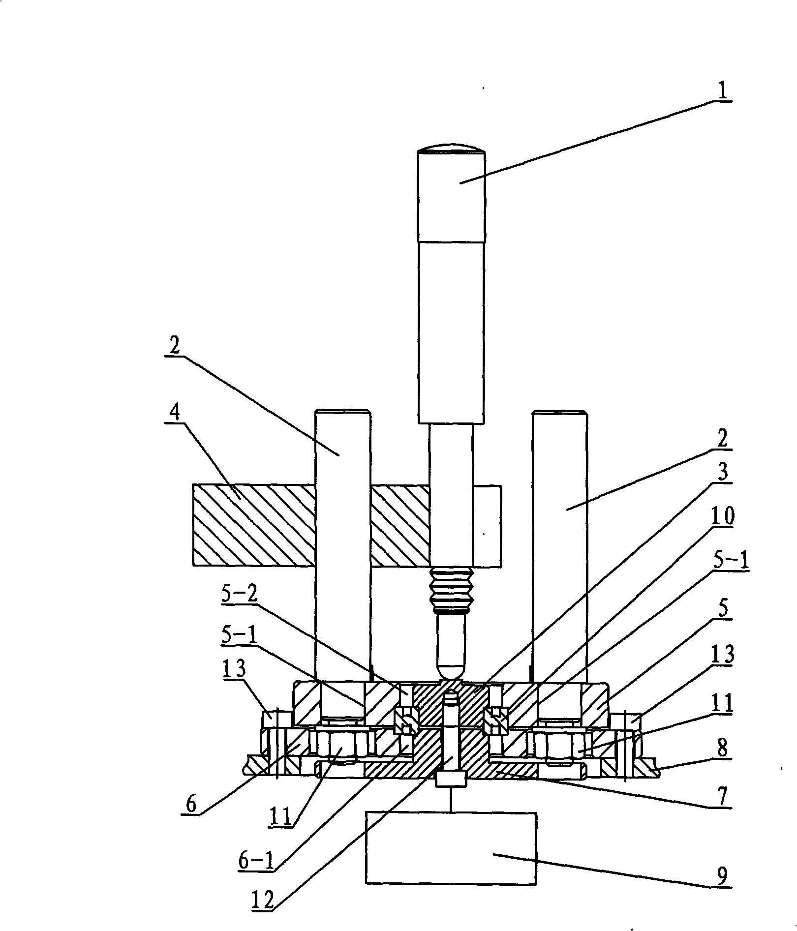
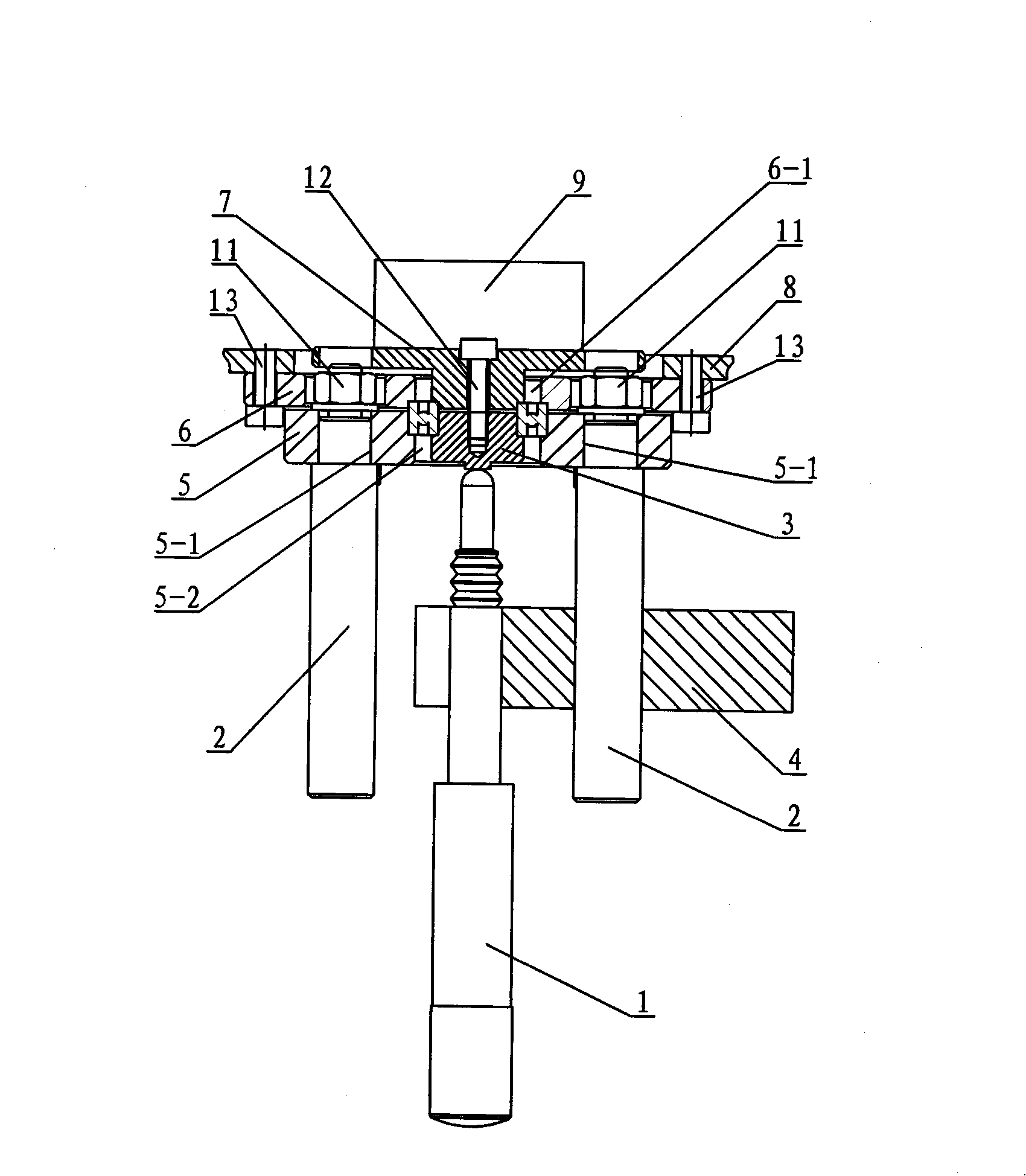
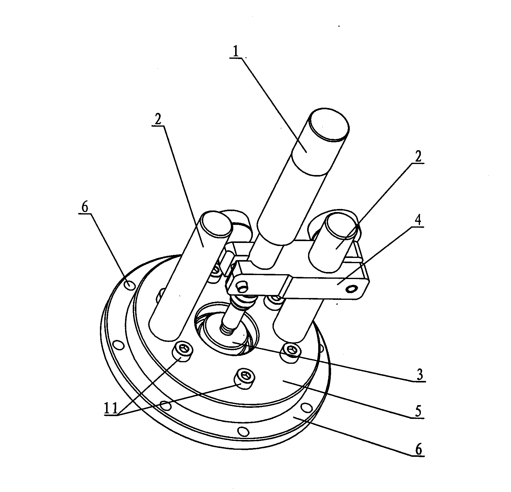
[0007] Specific implementation mode one: combine figure 1 and image 3 Describe this embodiment. This embodiment includes an inductive probe 1, two support rods 2, an inner ring pressure block 3, a connecting frame 4, a bearing seat 5, a connecting plate 6, a flange 7, a weight 9, and a first connecting piece 11 and the second connecting piece 12, one end of the two support rods 2 is respectively installed in the two support rod holes 5-1 on the bearing seat 5, and the inner ring pressure block 3 is installed in the center hole 5-2 on the bearing seat 5 Inside, one end of the connecting frame 4 is mounted on any one of the two supporting rods 2, the electric probe 1 is mounted on the other end of the connecting frame 4, and the probe end of the electric probe 1 is pressed against the inner ring pressure block 3 Corresponding to the central position of the contact surface, the connecting plate 6 is provided with a flange hole 6-1, the connecting plate 6 is detachably connected...

specific Embodiment approach 2

[0008] Specific implementation mode two: combination figure 1 Describe this embodiment. The difference between this embodiment and the first embodiment is that it also adds a support plate 8 and a third connecting piece 13. The support plate 8 is adjacent to the connection plate 6, and the connection plate 6 is located on the bearing seat 5. Between the support plate 8 , the large flange on the flange 7 is installed in the center hole of the support plate 8 , and the support plate 8 and the connecting plate 6 are detachably connected through the third connecting piece 13 . Design like this is to increase the intensity of connecting plate 6. Other components and connections are the same as those in the first embodiment.

[0009] Working principle: The outer ring of the tested bearing 10 is clamped by the bearing seat 5 and the connecting plate 6, and the inner ring of the tested bearing 10 is clamped by the inner ring pressure block 3 and the flange 7, and the outer ring of th...


PUM


Abstract

The invention relates to a bearing stiffness testing device, aiming at solving the problems of complex structure, inconvenient operation and high requirements on the surrounding environment of the existing bearing stiffness testing device. Ends of two studdles of the invention are respectively arranged at two studdle holes; an inner ring briquette is arranged in a central hole; one end of a connecting stent is positioned at any one studdle and an inductance probe is installed at the other end of the connecting stent; the probe end of the inductance probe is pressed on the center of a contact surface corresponding to the inner ring briquette; a connecting plate is connected with a bearing seat in a detachable manner through a first connecting piece, a flange is positioned in the central hole of the connecting plate and connected with the inner ring briquette in a detachable manner through a second connecting piece and a weight is connected with the flange. The testing device of the invention fixes the inner ring and the outer ring of the bearing to be tested respectively, loads on the inner ring to obtain the position deviation of the inner ring and the outer ring of the bearing under different load, thereby obtaining bearing stiffness index; in addition, the testing device has simple structure, convenient operation and relatively low requirements on the surrounding environment.

Description

technical field [0001] The invention relates to a bearing stiffness testing device. Background technique [0002] With the rapid development of my country's equipment manufacturing industry, higher and more precise requirements are put forward for the assembly of moving parts (especially the accurate realization of preload in the bearing assembly process). The accurate realization of the preload depends entirely on the accurate understanding of the axial stiffness of the bearing. The existing bearing stiffness measurement devices have problems such as complex structure, inconvenient operation, and high requirements on the surrounding environment, which limit their wide application in engineering practice. Contents of the invention [0003] The purpose of the present invention is to provide a bearing stiffness testing device to solve the problems of complex structure, inconvenient operation and high requirements on the surrounding environment of the existing bearing stiffn...

Claims


Application Information

Patent Timeline
Patent Type & Authority Applications(China)
IPC IPC(8): G01M13/04
Inventor 朱映远刘宏
Owner HARBIN INST OF TECH
Why Eureka
Try Eureka