Method and device for control bias of laser modulator

A laser modulator and bias control technology, applied in the field of communication, can solve the problems of long control time and slow convergence speed, and achieve the effect of improving accuracy and shortening stabilization time.

Active Publication Date: 2009-01-28
ZTE CORP
View PDF0 Cites 35 Cited by
  • Summary
  • Abstract
  • Description
  • Claims
  • Application Information

AI Technical Summary

Problems solved by technology

[0012] In view of this, the present invention provides a laser modulator bias control method and device to solve the problems of slow convergence speed and long control time in the bias control method in the prior art

Method used


Image

  • Method and device for control bias of laser modulator
  • Method and device for control bias of laser modulator
  • Method and device for control bias of laser modulator

Examples


Embodiment Construction

[0030] Functional Overview

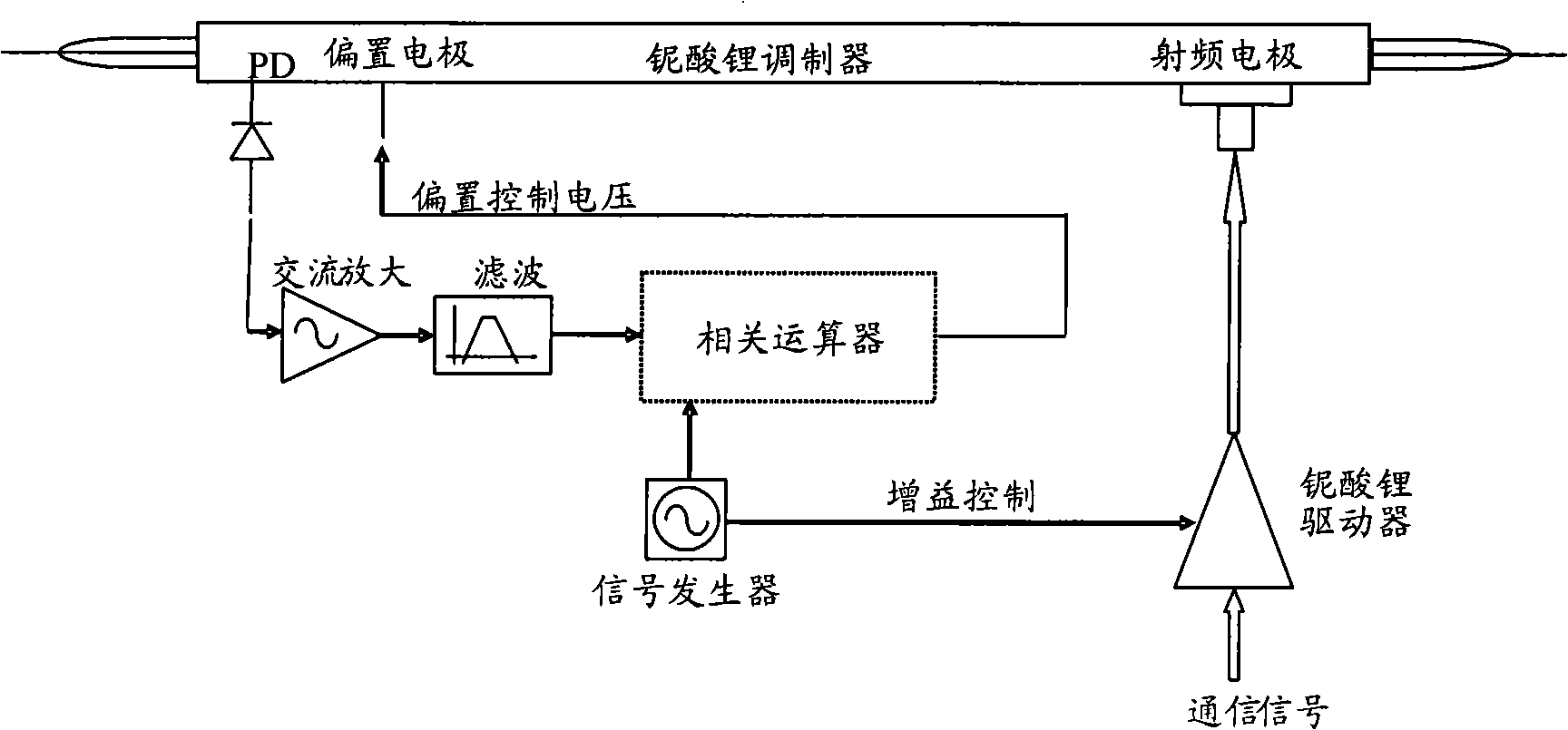
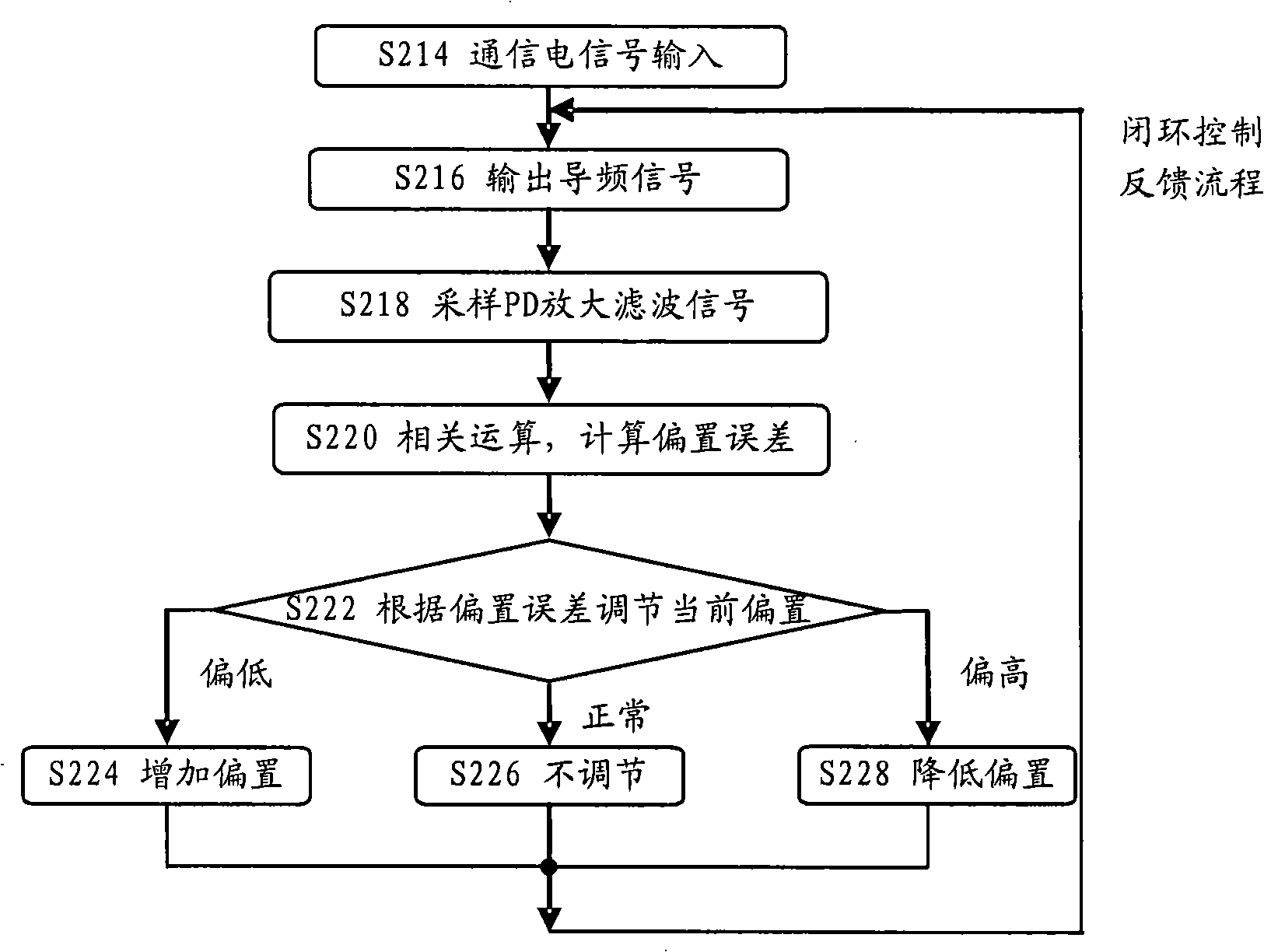
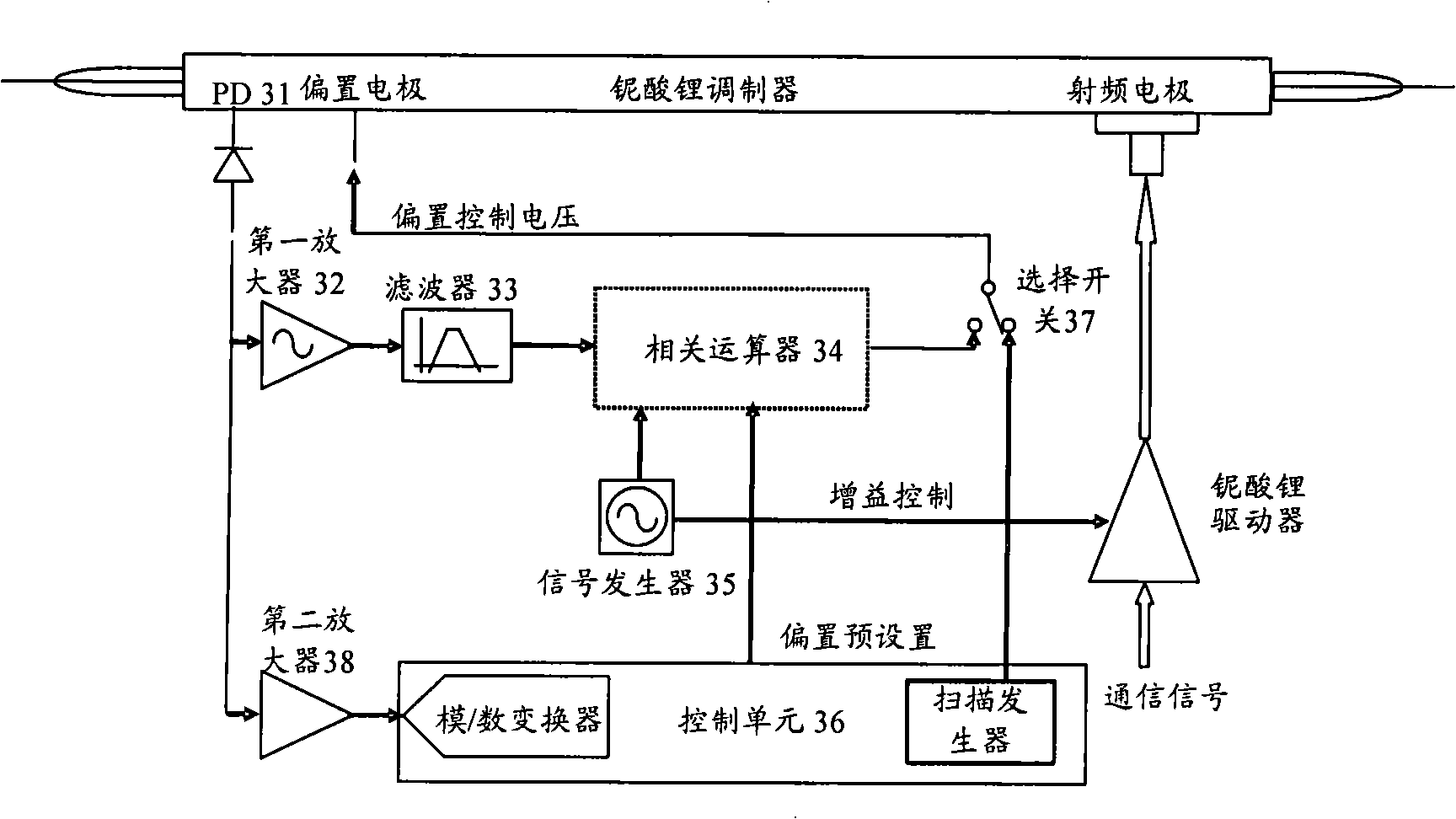
[0031] The present invention aims at the current problem that it takes a long time to achieve stable operation when the laser modulator is started, and proposes a laser modulator bias control scheme. In this scheme, when the laser modulator is started, the communication In the case of signal input, a linearly varying bias control voltage is input to the bias electrode of the laser modulator, and the input and output characteristics of the modulator are scanned to determine the bias control voltage corresponding to the preset operating point, and the bias The control voltage is initially biased to the control voltage, which is input to the bias electrode of the laser modulator during the normal working phase, and the closed-loop feedback control is performed on the laser modulator.

[0032] The preferred embodiments of the present invention will be described below in conjunction with the accompanying drawings. It should be understood that the prefer...


PUM


Abstract

The invention provides an offset control method and a device thereof. The method comprises the steps as follows: when the laser modulator is being started, linearly changed offset control voltages are input into the offset electrode of the laser modulator and the power of the output light of the laser modulator is obtained so as to determine the offset control voltage corresponding to the prearranged working point; subsequently, the communication electric signal of the radio frequency electrode of the laser modulator carries out the amplitude modulation of the communication electric signal by a low-frequency sine frequency guiding signal; simultaneously, determinate offset control voltage is input into the offset electrode; the output optical signal of the laser modulator is sampled and the sampled optical signal is compared with the frequency guiding signal; according to the comparison result, the offset control voltage of the offset electrode is adjusted. According to the technical proposal provided by the invention, the control stabilization time can be shortened and the control precision can be improved.

Description

technical field [0001] The invention relates to the field of communication technology, in particular to a bias control method and device for a laser modulator. Background technique [0002] Due to the advantages of high speed, large extinction ratio, high input optical power, adjustable chirp and insensitivity to wavelength, the external modulation method can increase the transmission distance of the WDM system and increase the transmission speed. Wide range of applications. However, due to the LiNbO-based 3 The operating point of the Mach-Zehnder (Mach-Zehnder) modulator of (lithium niobate) material is affected by temperature, mechanical stress, and device aging, and phase drift may occur, thereby affecting the performance of the output optical signal. Therefore, when using the modulator , it is necessary to perform feedback control on the bias (BIAS) operating point of the modulator to form a closed loop to ensure the stability of the bias. [0003] The traditional bia...

Claims


Application Information

Patent Timeline
Patent Type & Authority Applications(China)
IPC IPC(8): G02F1/35H04B10/12H04B10/50
CPCH04B10/50575G02F1/2255G02F1/0123G02F2203/21G02F1/0327
Inventor 沈剑青
Owner ZTE CORP
Why Eureka
Try Eureka