
Method for optimization regulation of receiver decision level and apparatus thereof

A technology of decision level and receiver, applied in electromagnetic receivers, electrical components, electromagnetic wave transmission systems, etc., can solve problems such as excessive deviation of decision level value, system frame loss, and long time consumption, and achieve improved stability. the effect of avoiding system business interruption

Inactive Publication Date: 2009-01-28
ZTE CORP
View PDF0 Cites 15 Cited by
  • Summary
  • Abstract
  • Description
  • Claims
  • Application Information

AI Technical Summary

Problems solved by technology

For a receiver with an automatic gain control function, the decision level value has nothing to do with the received optical power, the position of the decision level is close, and it only needs to be fine-tuned in a small range, so the existing automatic optimal adjustment methods for the decision level are all able to work stably
For a receiver without automatic gain control function, the decision level value is closely related to the received optical power. Therefore, when the received optical power changes greatly, the decision level value may deviate too much, and the system may experience frame failure. In the case of loss of (LOF), once LOF occurs, the existing various decision level automatic optimization adjustment methods must find a decision level that can eliminate the LOF state as the initial value through a global search method before the decision level can be adjusted. Optimizing adjustments, which will inevitably take a long time and cause long-term interruptions to the system

Method used


Image

  • Method for optimization regulation of receiver decision level and apparatus thereof
  • Method for optimization regulation of receiver decision level and apparatus thereof
  • Method for optimization regulation of receiver decision level and apparatus thereof

Examples


Embodiment Construction

[0020] In order to make the object, technical solution and advantages of the present invention clearer, the present invention will be described in detail below with reference to the accompanying drawings and specific embodiments.

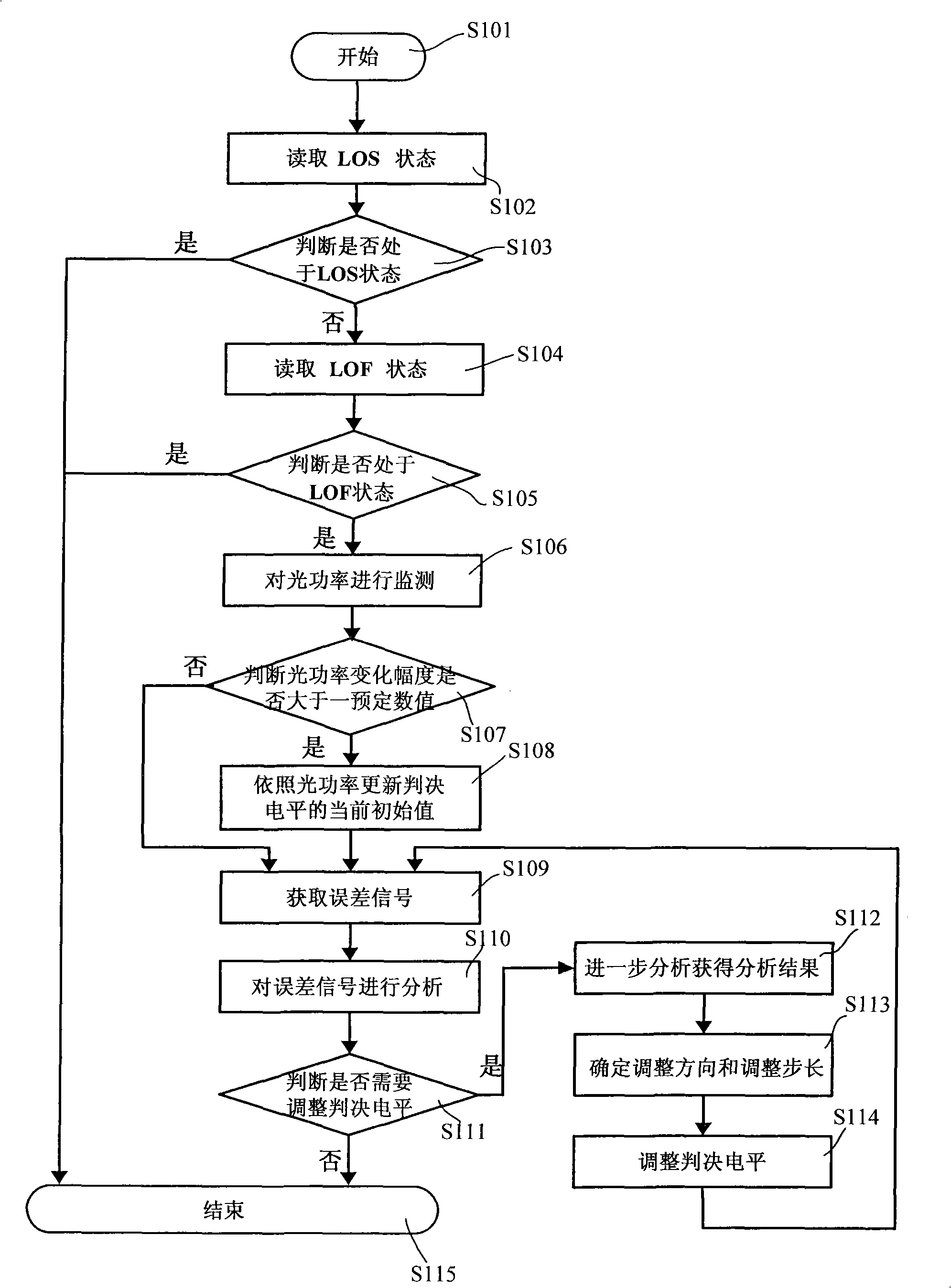
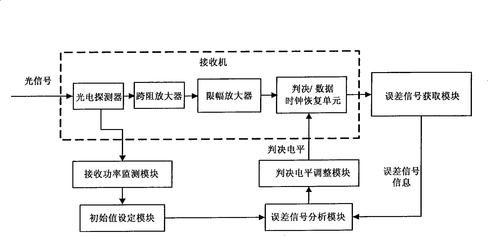
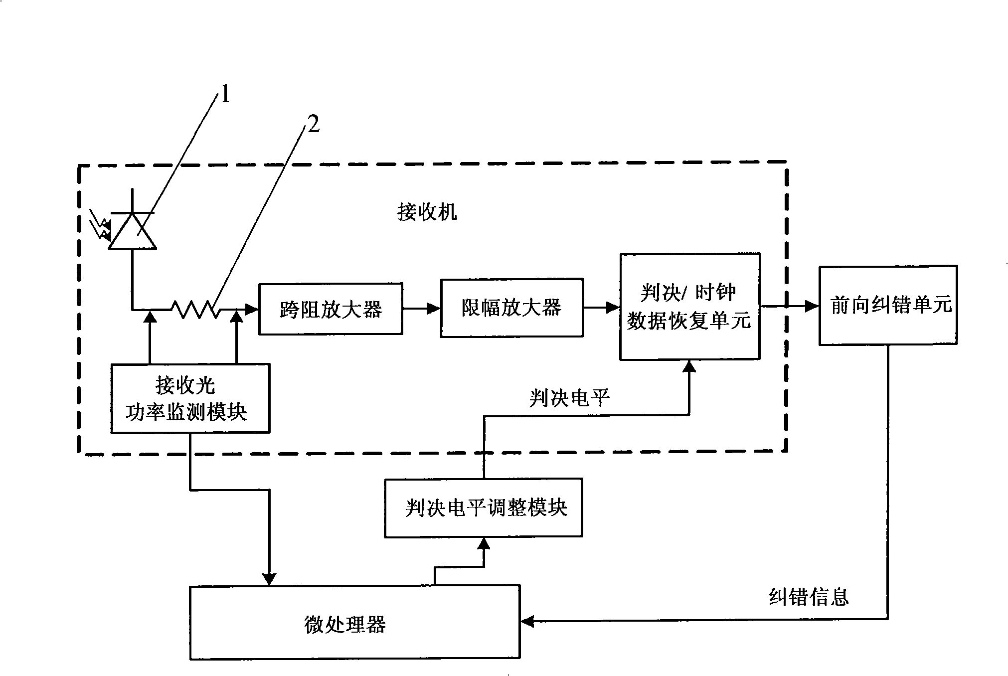
[0021] The method for optimizing and adjusting the decision level of the receiver described in the specific embodiment of the present invention monitors the optical power received by the optical receiver, and judges whether the variation range of the optical power is greater than a preset value; when the received optical power When the range of change is greater than the preset value, it is considered that the current decision level value may have a large deviation and cause system LOF, and the current initial value of the set decision level is updated based on the current received optical power; The error signal of the transmitted signal obtained by the optical receiver is used to determine whether the judgment level needs to be adjusted, and if the...


PUM


Abstract

The invention discloses a method for optimizing and adjusting the threshold level of a receiver and a device. The method comprises: the light power received by a light receiver is monitored; whether the amplitude of fluctuation of the light power is bigger than a preset value is judged, if yes, the present initial value of the threshold level is updated according to the light power; the error signal of the transmission signal is acquired from the output end of the light receiver; whether the threshold level needs to be adjusted is judged according to the error signal, if yes, according to the present initial value, the error signal is further analyzed, and the analysis result is acquired; if no, the execution program is directly jumped out; according to the analysis result, the threshold level is adjusted starting from the present initial value. The method and the device monitor the received light power, and set up the initial value of the threshold level according to the received light power, thereby avoiding the system service from being interrupted because of the long-time search of the initial value of the threshold level caused by the change of the light power, and greatly improving the stability of the system.

Description

technical field [0001] The invention relates to the field of digital communication systems, in particular to a method for optimally adjusting the decision level of a receiver in a digital communication system and a device for adjusting the decision level by using the method. Background technique [0002] Optimal adjustment of receiver decision level is an important technology to improve system performance in digital communication systems. Through optimal adjustment of decision level, the bit error rate of the system can be effectively reduced and the noise margin of the system can be improved. In a traditional electrical communication system or a back-to-back (Bk-Bk) optical communication system, the noise on signal 1 and signal 0 is basically the same, so the decision level can be at the average value, ie, 50%. However, for the optical communication system after transmission, due to the influence of factors such as noise generated by the optical amplifier, fiber dispersion,...

Claims


Application Information

Patent Timeline
IPC IPC(8): H04B10/158
CPCH04B10/695H04B10/07H04B10/60
Inventor 张琦
Owner ZTE CORP
Learn More