Lighting control for vehicle lighting device

A lighting control, vehicle technology, applied in the direction of headlights, signal devices, lighting devices, etc., can solve the problem of increased power burden, achieve load equalization, prevent failure, and achieve good balance

Active Publication Date: 2009-01-28
KOITO MFG CO LTD
View PDF1 Cites 9 Cited by
  • Summary
  • Abstract
  • Description
  • Claims
  • Application Information

AI Technical Summary

Problems solved by technology

[0007] In the prior art described above, when an abnormality occurs at the output terminal of the switching regulator, the operation of the switching regulator is stopped to protect the LED by detecting the abnormality. However, when using each semiconductor light source (LED) as a multifunctional lamp, For example, if high beam, turn signal, cornering, DRL (Daytime Running Light) and other lamps are composed, if it is a switching regulator, the power burden will increase
Also, even simply using multiple switching regulators, the power burden on one switching regulator increases

Method used


Image

  • Lighting control for vehicle lighting device
  • Lighting control for vehicle lighting device
  • Lighting control for vehicle lighting device

Examples


Embodiment Construction

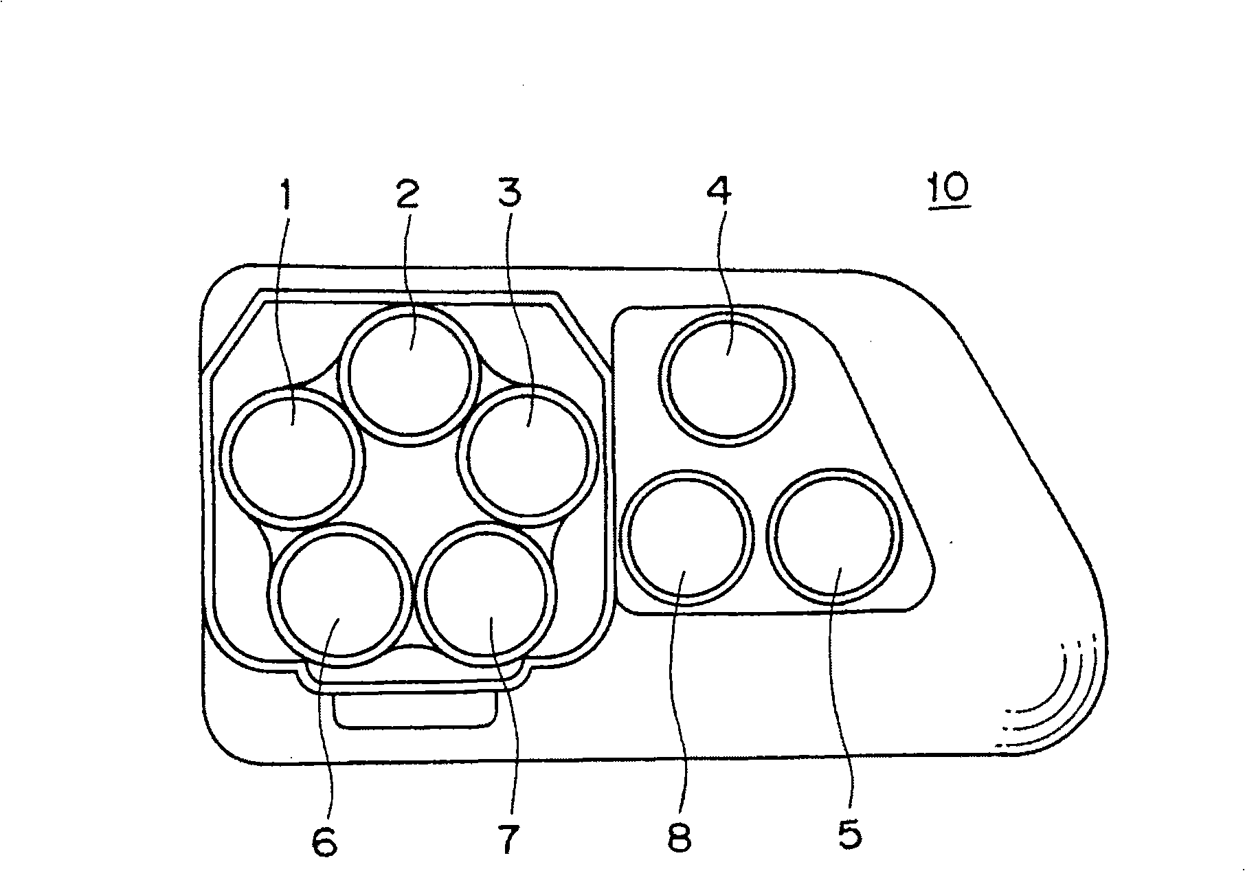
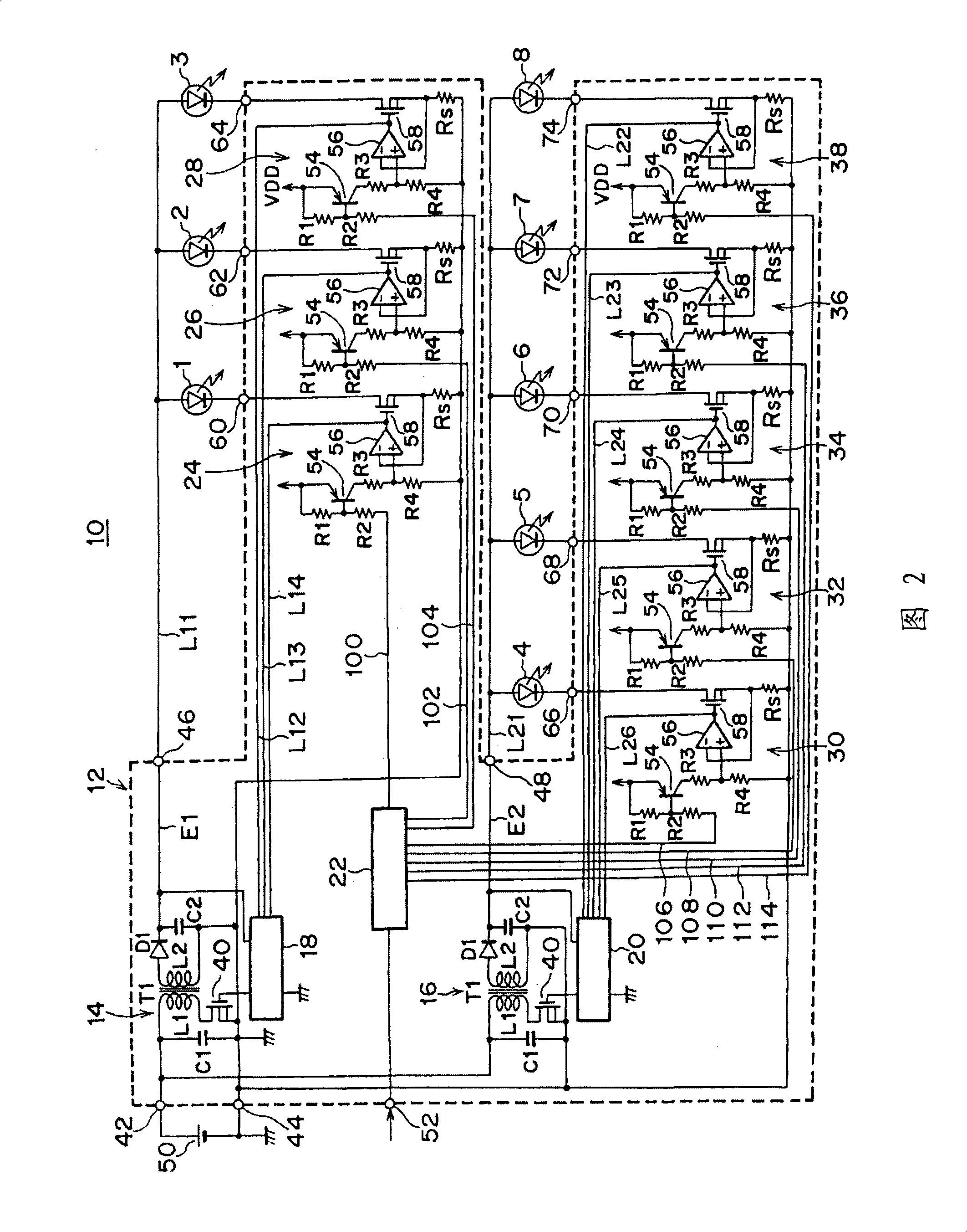
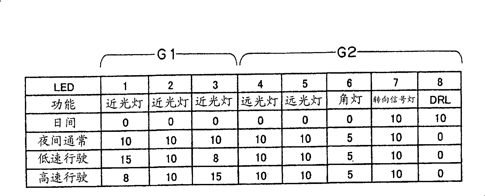
[0037] Hereinafter, an embodiment of the present invention will be described based on the drawings. figure 1 It is a front view of a vehicle lamp composed of a multifunctional lamp. FIG. 2 is a block diagram showing a lighting control device for a vehicle lamp according to an embodiment of the present invention. image 3 It is the first embodiment of the present invention, and is an explanatory diagram for explaining the relationship between various lighting patterns and the power of each LED when the LEDs used for the low beam headlights are all set to the same group, Figure 4 This is the second embodiment of the present invention, and is an explanatory diagram for explaining the relationship between various lighting patterns and the power of each LED when the LEDs used for the low beam headlights are divided into two groups.

[0038] figure 1 Among them, a vehicle lamp (light emitting device) 10 is a multifunctional lamp, and includes, for example, LED1 to LED8 constituting f...


PUM


Abstract

A lighting control device for a vehicle lighting device is arranged so that loads applied to switching regulators are about equal when driving multiple semiconductor light sources (e.g., LEDs) as multifunctional lamps through the switching regulators. The LEDs are divided into two groups. The LEDs belonging to the first group are driven to be turned ON through a first switching regulator and the LEDs belonging to the second group are driven to be turned ON through a second switching regulator. Maximum values of power to be supplied to the LEDs are set to be about equal to each other, and loads to be applied to the switching regulators are about equal to each other.

Description

Technical field [0001] The present invention relates to a lighting control device for a vehicle lamp, and more particularly, to a lighting control device for a vehicle lamp for controlling the lighting of a semiconductor light source composed of a semiconductor light emitting element. Background technique [0002] Conventionally, as a vehicle lamp, a lamp using a semiconductor light emitting element such as an LED (Light Emitting Diode) as a light source is known. Such a vehicle lamp is equipped with a lighting control device for controlling the lighting of the LED. [0003] As a lighting control device, there is known a series regulator that is connected in series to the LED to control a prescribed current to flow through the LED, and the output voltage applied to the LED is controlled to the minimum necessary according to the control state of the series regulator A device with a limited voltage switching regulator (switchingregulator). The switching regulator can control the ou...

Claims


Application Information

Patent Timeline
Patent Type & Authority Applications(China)
IPC IPC(8): H05B37/02B60Q1/00H05B44/00B60Q1/14H01L33/00
CPCH05B33/0827B60Q2400/30B60Q2300/112Y02B20/346H05B33/0815B60Q1/1423B60Q1/2607B60Q2300/146H05B45/46Y02B20/30H05B47/10H05B47/17H05B45/3725H05B45/395F21S41/00B60Q1/02H05B45/00
Inventor 北河孝悦中山彻野寄靖史
Owner KOITO MFG CO LTD
Why Eureka
Try Eureka