Power supply device, device and control method

A power supply device and equipment technology, applied in battery/fuel cell control devices, control/regulation systems, output power conversion devices, etc., can solve problems such as unoptimized switching, maintain control stability, simplify changes, and simplify actions The effect of changing the mode

Active Publication Date: 2021-04-20
HONDA MOTOR CO LTD
View PDF17 Cites 0 Cited by
  • Summary
  • Abstract
  • Description
  • Claims
  • Application Information

AI Technical Summary

Problems solved by technology

Therefore, switching the mode during the operation of the inverter device is not preferable in terms of control stability in this device.

Method used


Image

  • Power supply device, device and control method
  • Power supply device, device and control method
  • Power supply device, device and control method

Examples


no. 1 example

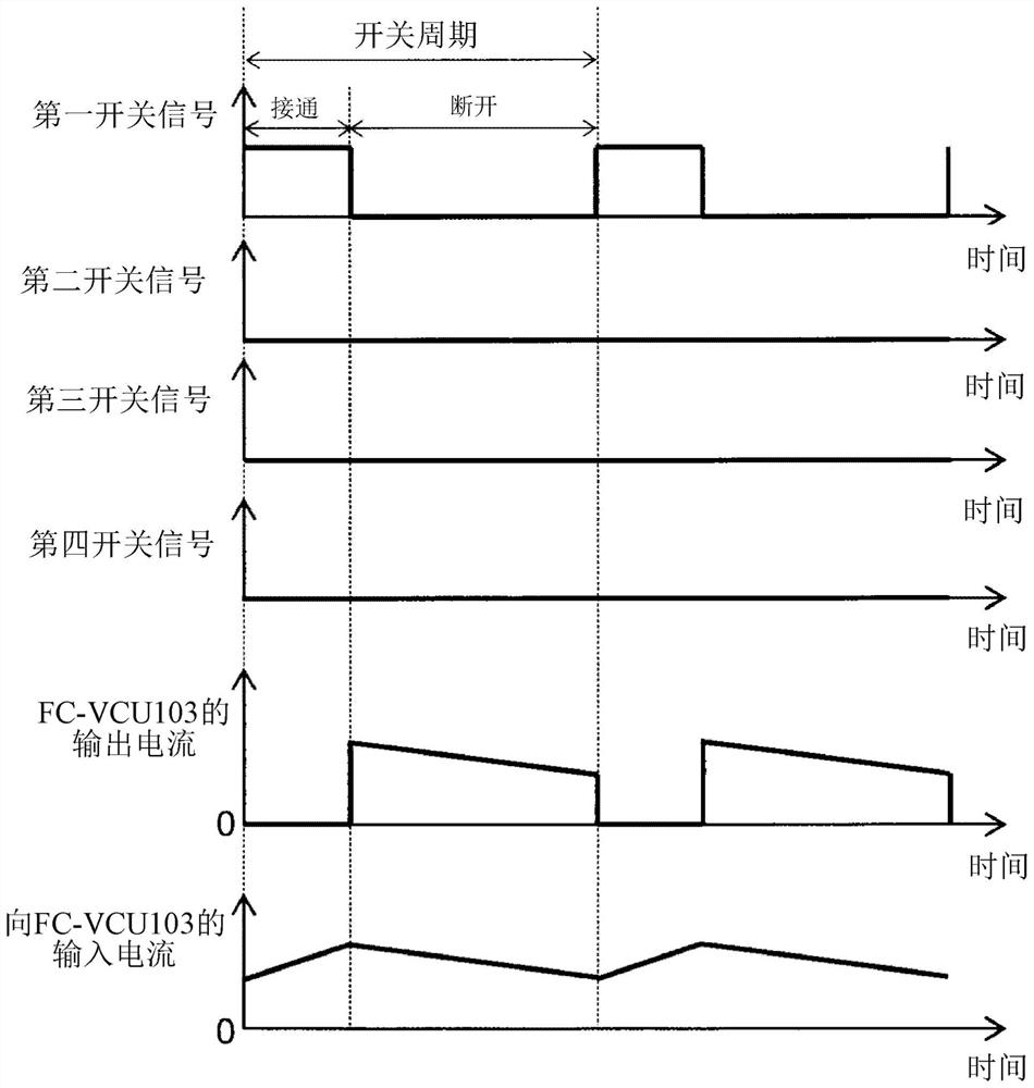
[0150] The ECU 113 of the first embodiment switches the driving modes of the phases in the FC-VCU 103 according to the on / off operation of the power switch 111 .

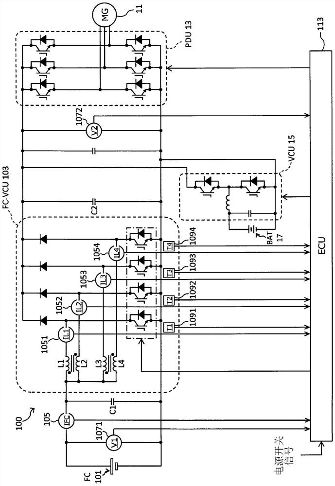
[0151] Figure 9 It is a diagram of the first embodiment showing the phases to be driven for each drive mode in the FC-VCU 103 in accordance with the number of operating phases. The ECU 113 of the first embodiment is based on Figure 9 FC-VCU103 is controlled by any one of the four drive modes shown. For example, when driving FC-VCU103 with 1 phase in driving mode 1, ECU113 performs on / off switching control for the switching element of phase 1, and controls phase 1 with a phase difference of 180 degrees when driving with 2 phases. Each switching element of Phase 1 and Phase 2 is controlled to be ON / OFF, and when driving with 4 phases, each switching element of Phase 1 to Phase 4 is controlled to be ON / OFF with a phase difference of 90 degrees. In the case of two phases, for example, "phase 1 and phase 2" or "phas...

no. 2 example

[0160] The ECU 113 of the second embodiment is driven by a 1-phase figure 2 and Image 6 In the illustrated magnetic coupling type FC-VCU 103 , the phase 2 or the phase 3 arranged on the inner side among the phases 1 to 4 arranged in a row on the XY plane is driven.

[0161] Figure 11 It is a diagram of the second embodiment showing the phases to be driven for each drive mode in the FC-VCU 103 in accordance with the number of operating phases. The ECU 113 of the second embodiment is based on Figure 11 FC-VCU103 is controlled by any one of the two drive modes shown. For example, when driving FC-VCU103 with 1 phase in drive mode 1, ECU113 performs on / off switching control for switching elements of phase 2, and controls phase 1 with a phase difference of 180 degrees when driving with 2 phases. Each switching element of Phase 1 and Phase 2 is controlled to be ON / OFF, and when driving with 4 phases, each switching element of Phase 1 to Phase 4 is controlled to be ON / OFF with...

no. 3 example

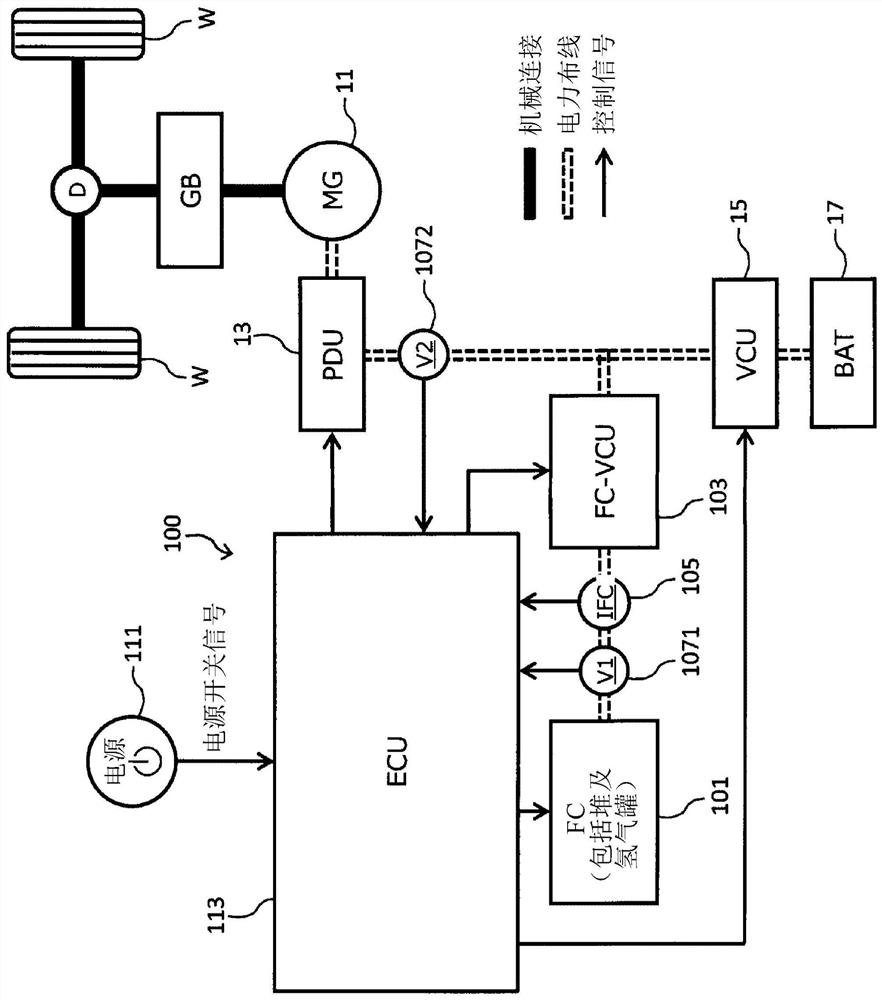
[0170] The ECU 113 of the third embodiment is based on the input current IFC to the FC-VCU 103 which is also the output current of the fuel cell 101, the input voltage V1 of the FC-VCU 103 which is also the output voltage of the fuel cell 101, and the FC-VCU 103 as a target value. The output voltage V2 of the pre-created loss distribution map only determines the number of operating phases of the FC-VCU103 based on the input current IFC. In addition, in the following description, "output voltage V2 / input voltage V1" is called the boost rate of FC-VCU103.

[0171] Figure 13 It is a graph showing the loss ηtotal_N in the FC-VCU 103 for each operating phase number N with respect to the input current IFC when the input power (=IFC×V1) of the FC-VCU 103 is constant. in addition, Figure 14 It is a graph showing the loss in the FC-VCU 103 with respect to the boost rate when the input power is constant and the FC-VCU 103 is driven with a predetermined number of phases. Such as F...


PUM


Abstract

The present invention provides a power supply device, equipment and control method. The power supply device includes: a power supply mounted on the equipment; a switch operated when starting or stopping the equipment; The conversion unit that performs voltage conversion of the electric power, and the plurality of conversion units are electrically connected in parallel; the selection unit, for each of the number of conversion units that perform voltage conversion, that is, the number of operations, selects the combination of conversion units that perform voltage conversion selecting one of the plurality of modes; and a control unit that controls the conversion module so that the conversion unit indicated by the mode selected by the selection unit performs voltage conversion. The selection unit changes the selected mode triggered by the operation of the switch. Regarding the plurality of modes, combinations of conversion units that perform voltage conversion differ from each other in at least one number of operations.

Description

technical field [0001] The invention relates to a power supply device, equipment and control method. Background technique [0002] The inverter device described in Patent Document 1 includes a plurality of DC voltage converters, and the driving sequence of the plurality of DC voltage converters is performed in an order determined in consideration of reducing variations in driving times and distributing heat generated during driving. The technique described in Patent Document 1 is also described in Patent Document 2. [0003] prior art literature [0004] patent documents [0005] Patent Document 1: Japanese Patent Laid-Open No. 2009-296775 [0006] Patent Document 2: Specification of German Patent Application Publication No. 10 2013 203 830 [0007] Patent Document 3: Japanese Patent Laid-Open No. 2014-11904 [0008] The problem that the invention wants to solve [0009] The converter device described in Patent Document 1 acquires a pattern of the switching order of th...

Claims


Application Information

Patent Timeline
Patent Type & Authority Patents(China)
IPC IPC(8): H02M3/155
CPCH01M8/0488H01M2250/20H02M3/1584H01M8/04302H01M8/04303H02M1/0032H02M1/0048H02M1/0064Y02B70/10Y02E60/50Y02T10/70Y02T90/40B60L58/40H01M8/04567H01M8/0491H02M1/32H02M3/1582H02M1/327
Inventor 北本良太
Owner HONDA MOTOR CO LTD
Why Eureka
Try Eureka