Resin condenser and house refuse disposer

A domestic garbage and condenser technology, applied in grain processing, steam condensation, chemical instruments and methods, etc., can solve problems such as large pressure loss, and achieve high-efficiency processing and good cooling effect

Inactive Publication Date: 2009-02-04
CHIKUMASEIKI
View PDF3 Cites 6 Cited by
  • Summary
  • Abstract
  • Description
  • Claims
  • Application Information

AI Technical Summary

Problems solved by technology

However, there are following problems, that is, such a drain pipe is usually provided with a deodorizer (トラツプ: trap) to prevent the reflux of the odor, and in addition, the drain pipe is s

Method used


Image

  • Resin condenser and house refuse disposer
  • Resin condenser and house refuse disposer
  • Resin condenser and house refuse disposer

Examples


Embodiment 1

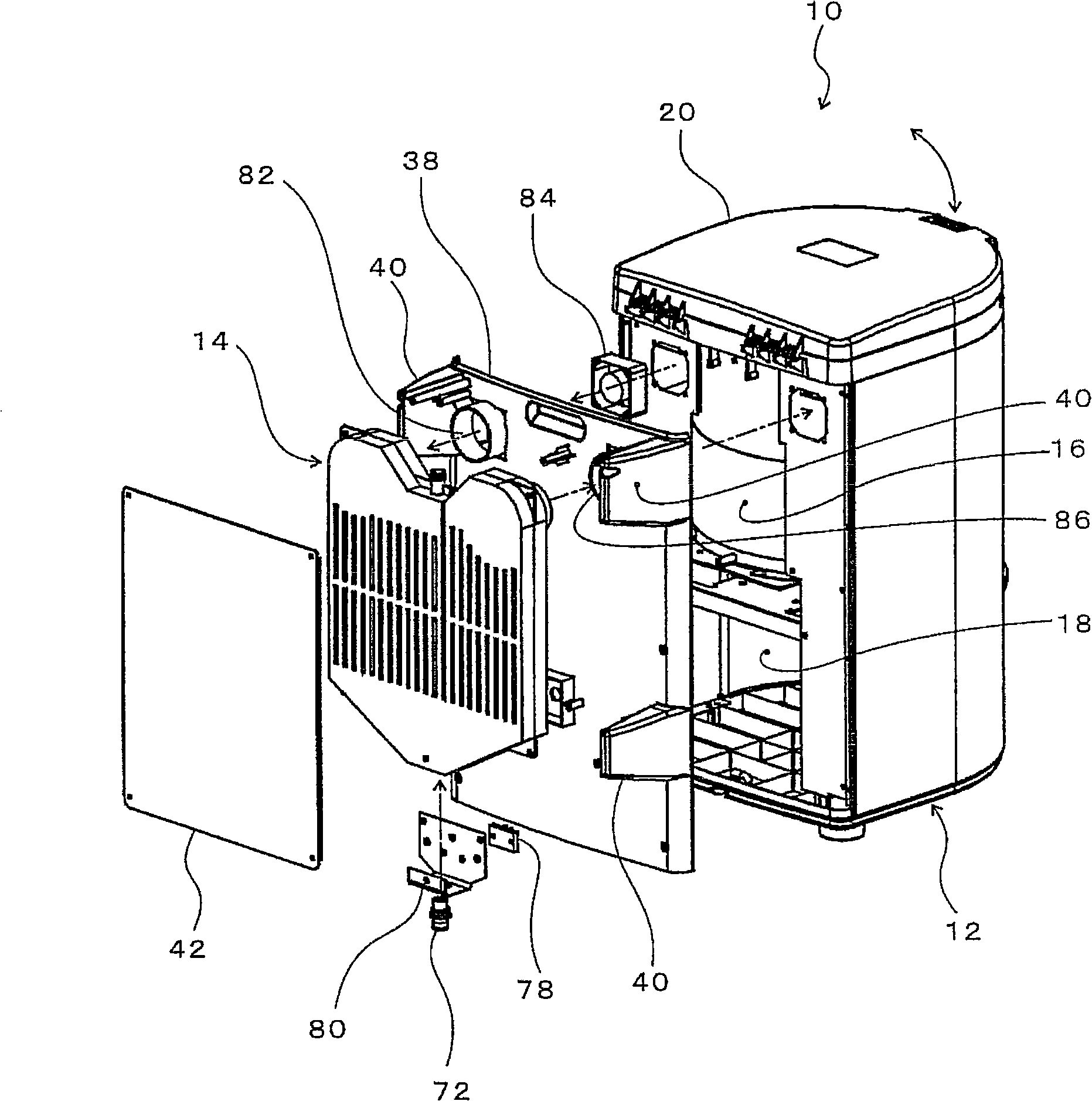
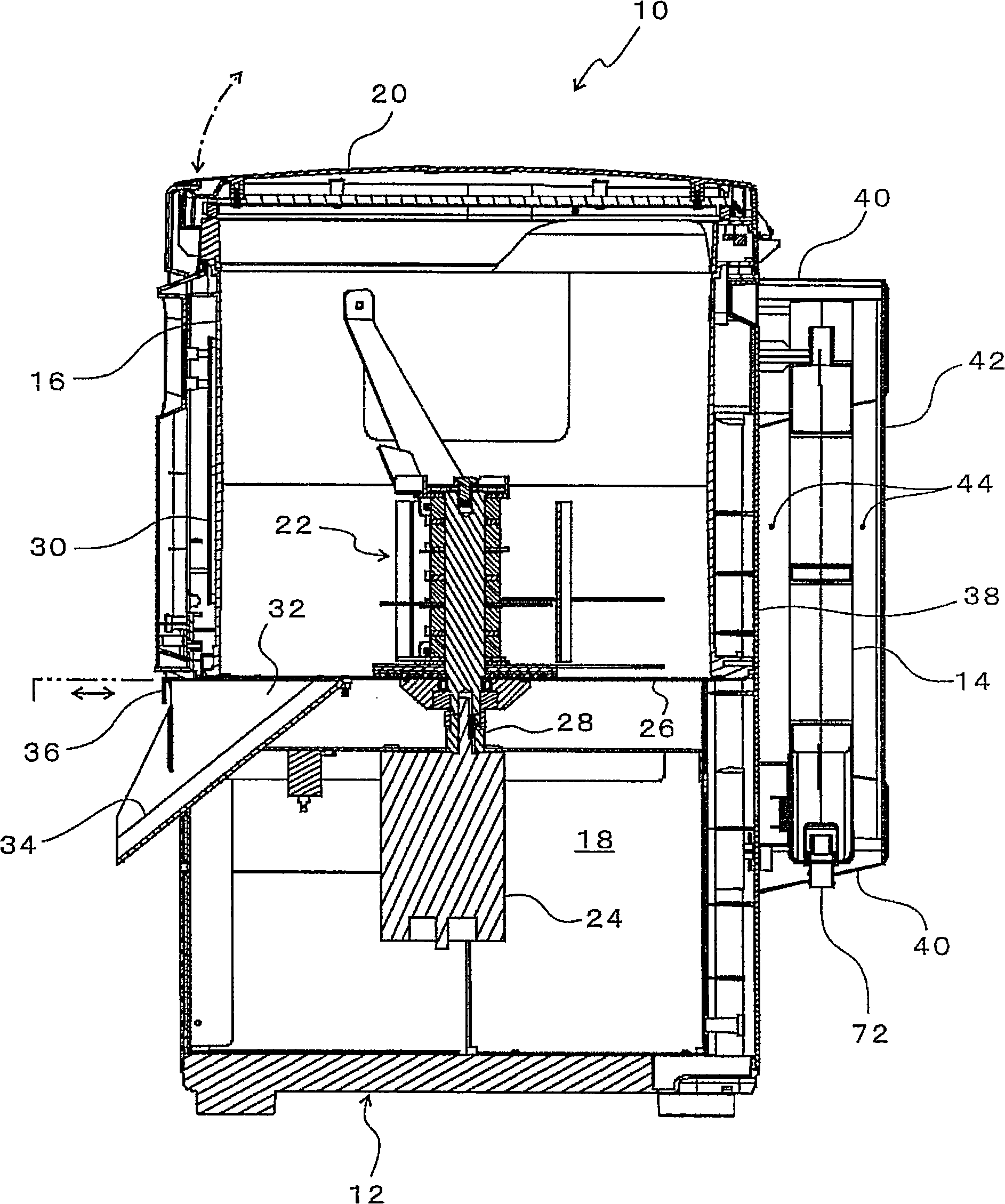
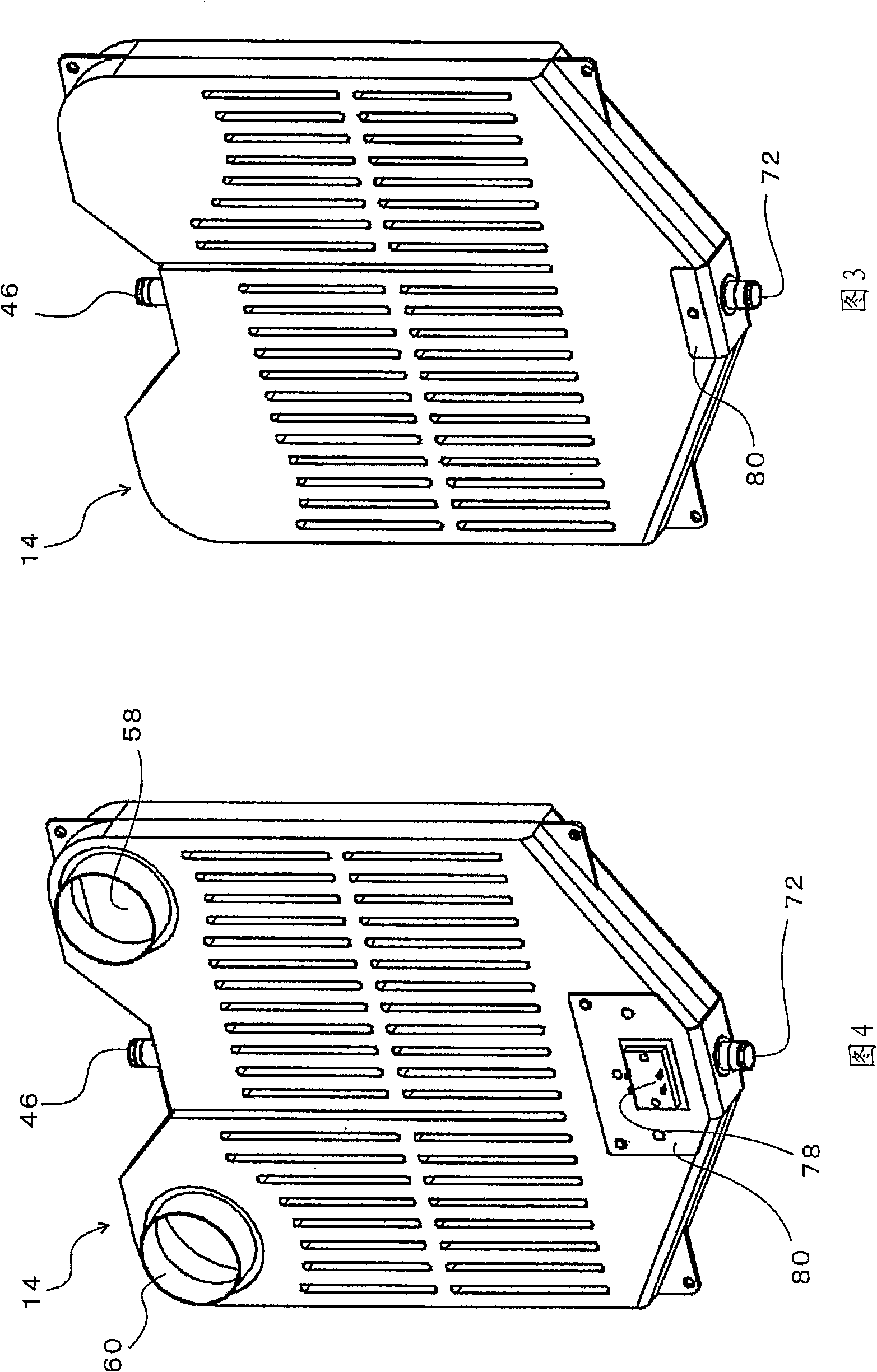
[0075] figure 1 It is an exploded perspective view of a domestic waste disposer as an embodiment of the present invention; figure 2 is a side sectional view; Fig. 3 is a front perspective view of the condenser; Fig. 4 is a back perspective view of the condenser; Figure 5 is the front view of the condenser; Figure 6 is the top view of the condenser; Figure 7 is the bottom view of the condenser; Figure 8 is along Figure 5 The cross-sectional view of the IIX-IIX line in the figure; Figure 9 is along the Figure 5 Sectional view of line IX-IX in; Figure 10 is along Figure 5 The cross-sectional view of the X-X line in; Figure 11 is along Figure 5 The cross-sectional view of the XI-XI line in; Figure 12 is an exploded perspective view of the deodorizer; Figure 13 It is a cross-sectional perspective view of an assembled state of the deodorant.

[0076] exist figure 1 , 2 Among them, reference numeral 10 is a domestic waste disposer, which is composed of a dom...

Embodiment 2

[0092] Figure 14 It is a cross-sectional view showing still another example of the deodorizer. In this deodorant 100, on the one hand, the plug 104 can be installed on the blow-molded deodorant mounting hole 102 from below or removed, on the other hand, the drain pipe 106 that runs through the plug 104 The upper part is generally in an inverted U shape and bends downward.

Embodiment 3

[0094] Figures 15-18 It is a figure which shows still another Example. Figure 15 is equivalent to that of the above-mentioned Example 1 along the Figure 5 A cross-sectional view of the position of the IIX-IIX line in; Figure 16 is equivalent to Example 1 along the Figure 5 The sectional view of the position of the IX-IX line in; Fig. 17 is along the line equivalent to embodiment 1 Figure 5 The cross-sectional view of the position of the X-X line in; Figure 18 is equivalent to Example 1 along the Figure 5 Sectional view of the location of the XI-XI line.

[0095] In the case of the condenser 14 of the first embodiment described above, the grooves 65 are sunken from both the front and back surfaces of the condenser 14 between the gas cooling passages 54 on the inflow side and the gas cooling passages 56 on the exhaust side, and are recessed. The bottoms of the grooves 65 abut one another. However, by doing so, as described above, the resin is narrowed between the ...


PUM


Abstract

A condenser is provided that can discharge condensate liquid smoothly without worrying about surrounding spread of bad smell, and has simple structure and the small number of components, thus adapting to miniaturization. The condenser is provide with: a plurality of gas cooling channels (54), (56) that are mutually communicable and allow for pass-through of gases comprising steam; a liquid collection chamber (48) which collects the condensate liquid liquefied in the gas cooling channels (54), (56), wherein bottom of the liquid collection chamber (48) is provided with a deodorant device (66) that not only allows for discharging of the condensate liquid, but also restricts discharging of the gases, in the other hand, mounting holes (68) of the gas cooling channels (54), (56), the liquid collection chamber (48) and the deodorant device (66) integrally form a resin-made condenser and a household garbage treater by resins by means of blow molding.

Description

technical field [0001] The present invention relates to a condenser that cools gas containing water vapor and the like through a gas cooling passage, stores condensate and discharges it, and a domestic garbage disposer using the condenser. Background technique [0002] Conventionally, there is known a household garbage disposer which disposes household garbage such as waste left over from cooking and leftovers by cutting them into small pieces to reduce its capacity. In particular, a domestic waste disposer for general households is known. There are various ways of this domestic waste disposer, and the dry type domestic waste disposer is one of them. Patent Documents 1 and 2 disclose such a dry-type domestic waste disposer. [0003] (Patent Document 1) JP-A-59-162954 [0004] (Patent Document 2) JP-A-2004-298773 [0005] The treatment method of this dry-type domestic waste disposer is that on the one hand, it cuts and heats the domestic waste while stirring, on the other...

Claims


Application Information

Patent Timeline
IPC IPC(8): B01D5/00B02C18/06
Inventor 百瀬和弘田中正彦吉沢彰
Owner CHIKUMASEIKI
Why Eureka
Try Eureka