Laser marking label

A laser marking and marking technology, used in instruments, programming, layered products, etc., can solve the problems of insufficient durability, difficult white line patterns, poor resolution and resolution, and achieve good shading effect.

Inactive Publication Date: 2009-02-04
NITTO DENKO CORP
View PDF1 Cites 15 Cited by
  • Summary
  • Abstract
  • Description
  • Claims
  • Application Information

AI Technical Summary

Problems solved by technology

However, the thermal transfer method has the following disadvantages: insufficient durability, poor resolution, especially the resolution of two-dimensional codes, and difficulty in drawing white line patterns on a black background, etc.
In thermal transfer printing, it is difficult to display white lines especially on a black background, and it shows insufficient durability, and it shows insufficient resolution in two-dimensional codes with small unit sizes, etc. Therefore, it is preferable to use laser marking markings, however, are not sufficiently opaque

Method used


Image

  • Laser marking label
  • Laser marking label

Examples


Embodiment 1

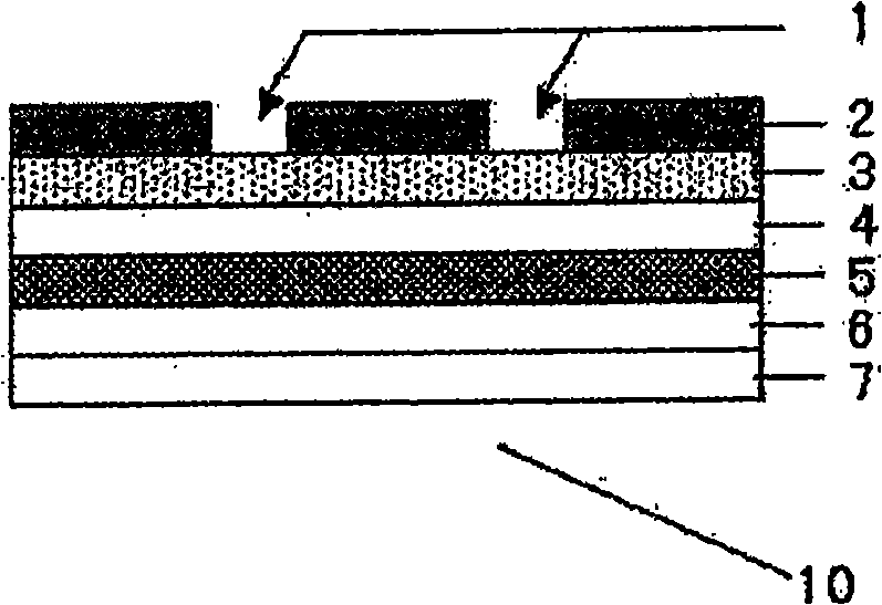
[0039] On both sides of the transparent PET film (Toray, lumirror S10, thickness 50μm) used as the support layer, the gravure printing (manufactured by Toshiba Machine Co., Ltd.) with black gravure ink (NB-300 manufactured by Dainichi Seika Co., Ltd.) was formed on one side to form 2μm. On the other side of the recording layer, use white gravure ink (NB-300 manufactured by Dainichi Seika Co., Ltd.) to form a base layer of 2μm in gravure printing, and use commercially available silver screen ink for screen printing (NEWLONG Precision Kogyo Co., Ltd.) After forming a 10μm light-shielding layer, an adhesive (acrylic type, thickness of 50μm) / separator (PET, thickness of 75μm) (manufactured by Nitto Denko, both sides / T LA- 50) As the adhesive layer and release liner, make laser marking marks. For this laser marking mark, use the KEYENCE laser marking machine MD-V9610 at 10J / cm 2 Under the laser irradiation conditions, a two-dimensional code with a cell size of 120μm is printed out. In ...

Embodiment 2

[0041] For both sides of the white PET film (Toray, lumirror E20, thickness 38μm) that becomes the support and base layer, gravure printing with black gravure ink (manufactured by Toyo Ink, Finestar) is used on one side to form a 2μm recording layer. The light-shielding layer (thickness: 50 nm) was formed by aluminum vapor deposition (using a roll-to-roll vacuum vapor deposition device manufactured by ULVAC Co., Ltd.) on one side, and it was carried out in the same manner as in Example 1 except that.

Embodiment 3

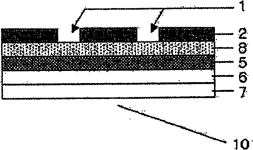
[0043] For both sides of the transparent PET film (Toray, lumirror S10, thickness 50μm) used as the support layer, a 2μm recording layer was formed on one side by gravure printing with white gravure ink (NB-300 manufactured by Dainichi Seika Co., Ltd.). On the other side, gravure printing with black gravure ink (NB-300 manufactured by Dainichi Seiki Co., Ltd.) is used to form a 2μm base layer, and aluminum vapor deposition is used to form a light-shielding layer (thickness 50nm) on the base layer side. Example 1 was implemented in the same way.


PUM

PropertyMeasurementUnit
thicknessaaaaaaaaaa
thicknessaaaaaaaaaa
thicknessaaaaaaaaaa

Abstract

The present invention relates to a laser marking label for forming patterns by a process including the step of selectively destroying a recording layer with a laser beam and exposing lower layers, wherein the laser marking label contains at least a recording layer, a backing layer, a ground layer, a shielding layer, and an adhesive layer, in this order, wherein each of the layers is directly or indirectly laminated. According to the laser marking label of the present invention, patterns of a workpiece or an opening part can be covered for the designing property and prevention of erroneous operation of an optical sensor, and the label can also serve as a display, in other words, excellent shielding ability in both line image portions and non-line image portions can be provided.

Description

Technical field [0001] The present invention relates to a display label for recording with laser light. Background technique [0002] As a method of displaying information on a part or product, a direct printing method, an engraving method, a marking method, etc. are well-known. Due to restrictions on the combination of product materials and printing ink materials, or difficulty in printing on products of various shapes, difficult to variable information printing, etc., the direct printing method can only be used under limited circumstances. Regarding the marking method, in recent years, a method called laser marking (laser marking) to directly mark information on a product using a laser has been implemented. However, in the case of not wanting to damage the product due to strength or appearance problems , Or if you want to change the displayed information, it cannot be used. Therefore, the most commonly used method is the labeling method (Patent Document 1). [0003] Various pri...

Claims


Application Information

Patent Timeline
Patent Type & Authority Applications(China)
IPC IPC(8): B41M5/24G09F3/00B32B5/00
CPCB41M5/24G09F3/00G09F3/02
Inventor 天野恒行井元崇中平理惠
Owner NITTO DENKO CORP
Why Eureka
Try Eureka