
Device for simultaneous handling of several multi-filament threads

A technology for simultaneous processing and multifilament yarns, applied in textile and papermaking, etc., can solve the problems of difficult control, low efficiency, monitoring cross-section, etc., and achieve the effect of low production cost

Inactive Publication Date: 2009-02-04
OERLIKON HEBERLEIN TEMCO WATTWIL
View PDF10 Cites 2 Cited by
  • Summary
  • Abstract
  • Description
  • Claims
  • Application Information

AI Technical Summary

Problems solved by technology

[0013] DE102004007073 provides a yarn trough, it is actually very difficult to control and cannot be directly approached to monitor the cross section
According to the configuration of the lead-through groove shown in Fig. 6 in DE10 2004007073, the efficiency is actually very low

Method used


Image

  • Device for simultaneous handling of several multi-filament threads
  • Device for simultaneous handling of several multi-filament threads
  • Device for simultaneous handling of several multi-filament threads

Examples


Embodiment Construction

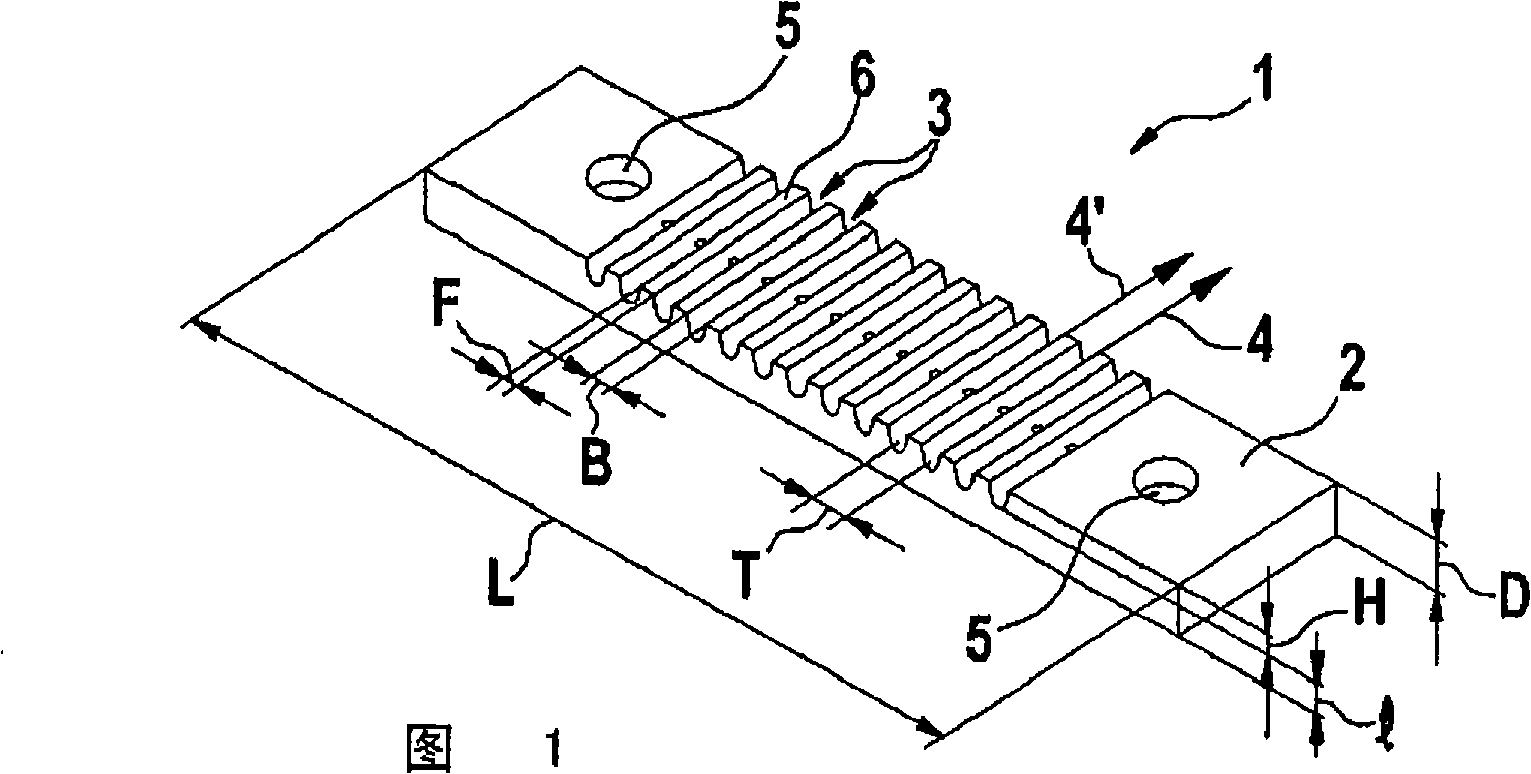
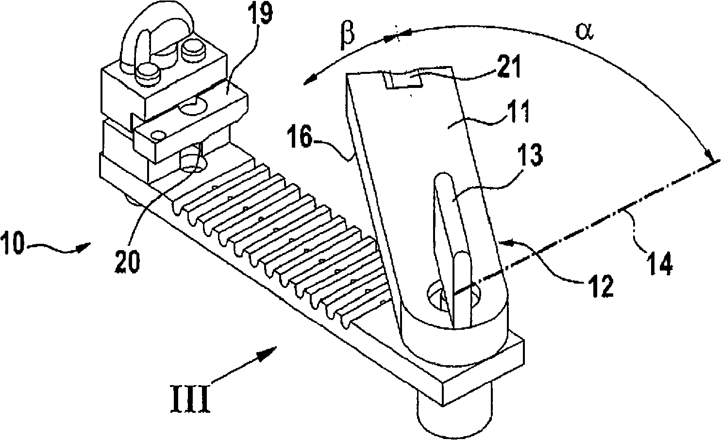
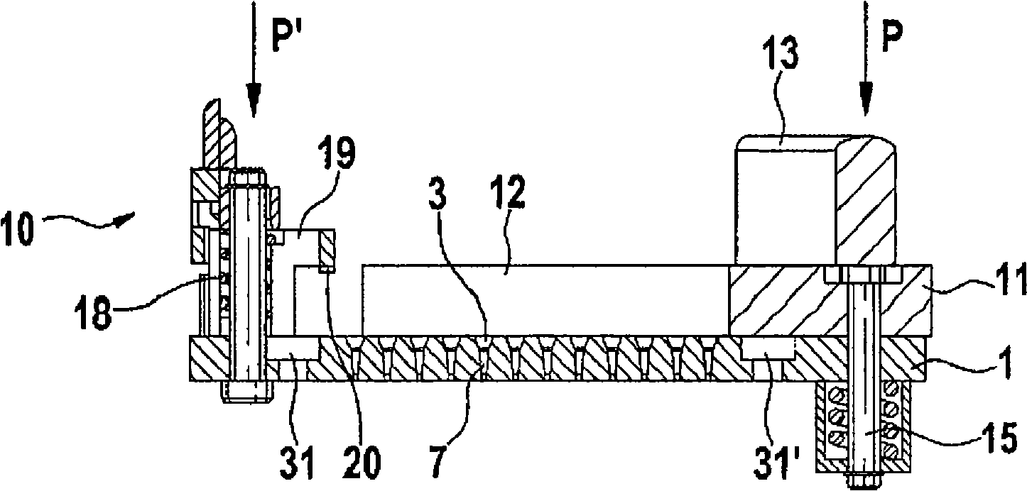
[0057] FIG. 1 shows a nozzle body 1 . The nozzle body 1 is a flat elongated plate 2 on which twelve yarn grooves 3 are introduced. In most cases, all yarn slots 3 of the present application are arranged in parallel, corresponding to the yarn directions 4, 4'. Holes 5 for fastening screws are provided on both lateral end faces of the plate 2 . The thickness of the nozzle body 1 is denoted by D. On the one hand, the thickness D is as important as the height H of the yarn groove 3, and on the other hand, the length 1 of the air duct 7 (see image 3 ) can be fixed or freely preferred. The yarn course or the division of the yarn groove 3 is indicated by T. The overall length of the plate 2 is denoted by the letter L and depends on the number and width B of the thread grooves 3 and the width F of the corresponding surface portion between two thread grooves 3 . In the case of twisting nozzles or moving nozzles, the air duct 7 ( image 3 ) vertically or obliquely. The shape and...


PUM


Abstract

The invention relates to a novel apparatus used for simultaneously treating a plurality of multifilament yarns in yarn channels (3) through a spinning nozzle (10), at least one air supply pipe (7) is installed in each yarn channel (3). The spinning nozzle (10) is designed to split a nozzle into two parts, having a basic body or a nozzle body (1) with yarn channel (3) and corresponding air supply pipe (7). The air supply pipe (7) is guided into the yarn channel (3). The novel apparatus can provide a yarn channel cross section configuration used for a single best nozzle, and have the same knot quality as the single nozzle. The apparatus can be used in the spinning process, or the threading device, or the warping machine.

Description

technical field [0001] The invention relates to a device for simultaneously processing a plurality of multifilament yarns in parallel yarn grooves through a spinneret, at least one air delivery pipe is installed for each yarn groove. Background technique [0002] When producing synthetic multifilament yarns, the yarns consist of a large number of ultrafine linear filaments. Melt-spun yarns produced in this way are also called flat filament yarns and form tows consisting of multiple filaments. Multifilament yarns are treated with compressed air in order to achieve cohesion between the filaments for subsequent production. This yarn can be textured during the spinning process and downstream processes. Textured yarns are twisted for the same reasons as flat yarns. [0003] In particular, two processing methods are known: [0004] In twisting, the loose structure of composite filaments (flat or textured yarns) creates knotted yarns. Knots are only strong during the movement ...

Claims


Application Information

Patent Timeline
IPC IPC(8): D02G1/16D02J1/08
CPCD02J1/08D02G1/161
Inventor C·西门P·巴克米勒
Owner OERLIKON HEBERLEIN TEMCO WATTWIL
Learn More