Remote sensing image fusion method

A fusion method and remote sensing image technology, applied in the field of remote sensing image fusion, can solve the problems of no application in the field of remote sensing image fusion, staying at the image processing level, and no general sensor model.

Inactive Publication Date: 2009-02-04
BEIJING NORMAL UNIVERSITY
View PDF0 Cites 11 Cited by
  • Summary
  • Abstract
  • Description
  • Claims
  • Application Information

AI Technical Summary

Problems solved by technology

However, most of the theoretical explanations of these methods stay at the pure image processing level, and there is no general sen

Method used


Image

  • Remote sensing image fusion method
  • Remote sensing image fusion method
  • Remote sensing image fusion method

Examples


Embodiment 1

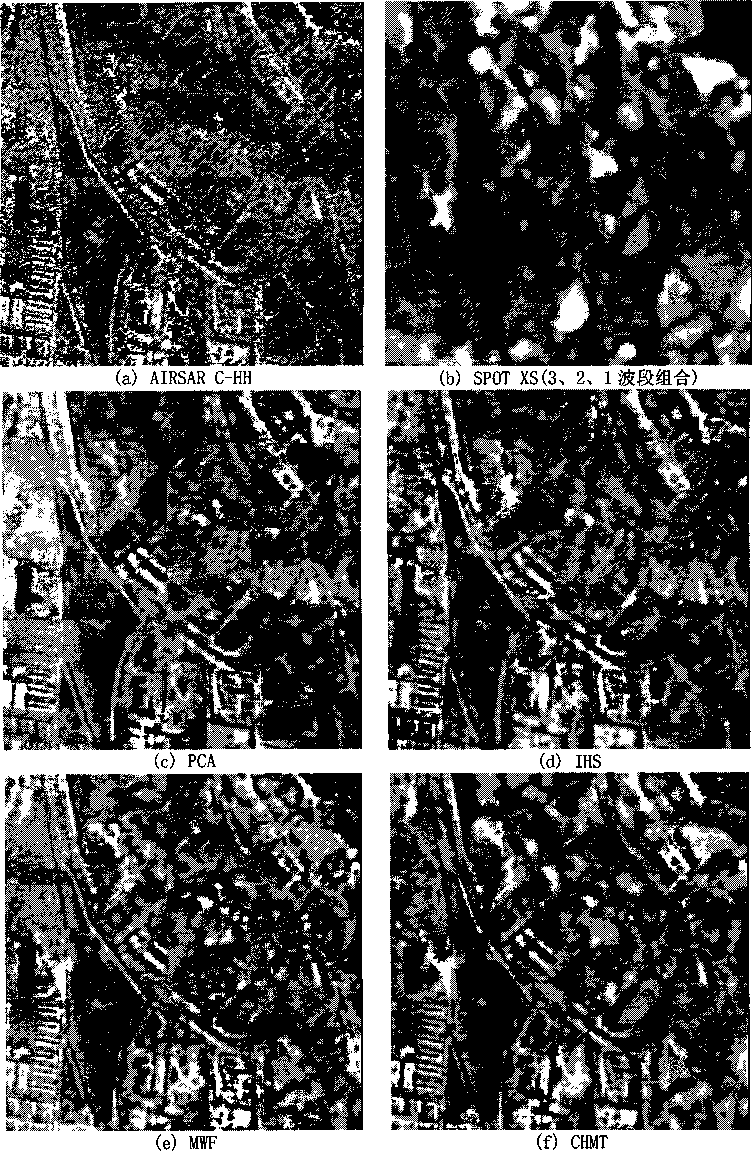
[0080]For the fusion of SAR and visible light images, the AIRSAR C-band HH polarization image is used as the SAR image, and its resolution in the range direction is about 6 meters, and the resolution in the azimuth direction is about 9 meters. figure 1 (a); The combination of bands 3, 2, and 1 of SPOT4 XS images is used as a multispectral image with a spatial resolution of 20 meters, such as figure 1 (b);

[0081] I. Resampling the AIRSAR image to 9m×9m; after registering the SPOT4 XS image with the AIRSAR image, resampling to 9m×9m;

[0082] II. Apply the principal component transformation to the data of the 4 bands of the AIRSAR image and the SPOT4 XS image to obtain the first principal component component PC 1 ;

[0083] III. For the first principal component PC 1 Use the CHMT model for training to obtain the conditional probability p(m|l k,m , θ o ) and u k,m ;

[0084] IV. On a certain scale direction band decomposed by Contourlet l k The maximum a posteriori esti...

Embodiment 2

[0095] Embodiment 2: Remote sensing image fusion method of the present invention

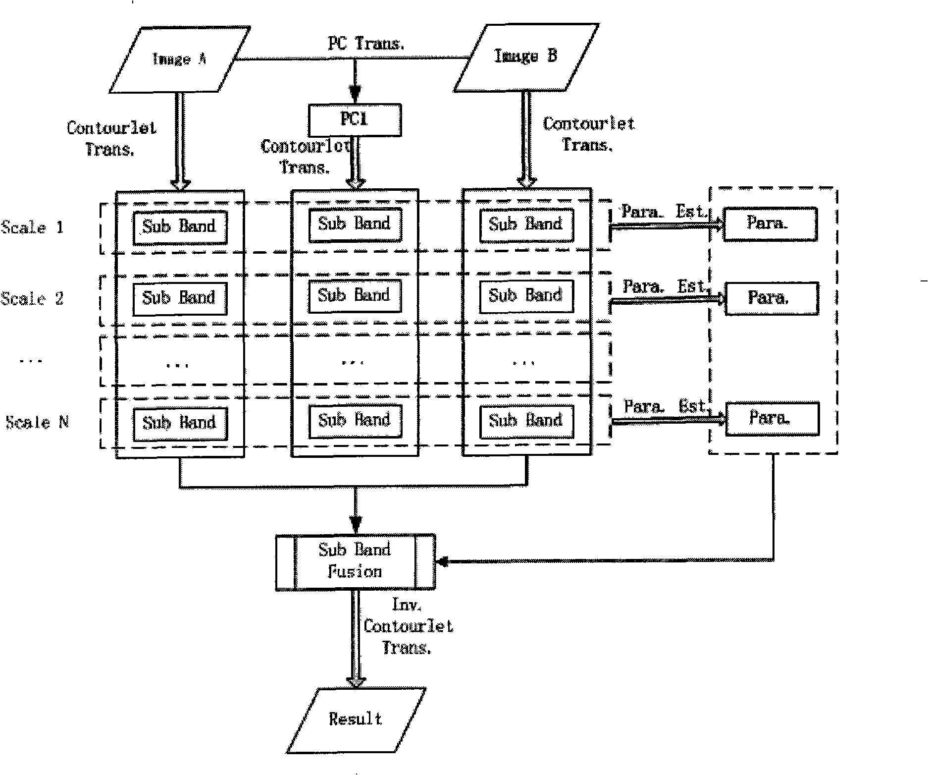
[0096] A. Establish a general sensor model in the Contourlet domain, which can be expressed as:

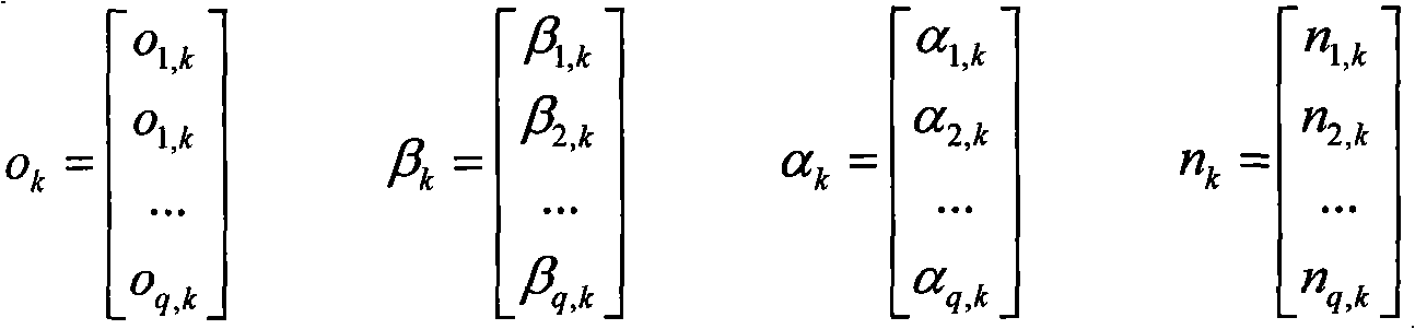
[0097] o i,k = β i,k l k +α i,k +n i,k Formula 1)

[0098] Among them, i=1, 2, ..., q is the number of sensors, which can also be considered as the number of bands to be fused, k represents the position, that is, the transformed Contourlet coefficient is in a certain direction sub-band corresponding to a certain scale position, l k is the value of the actual scene L at k after Contourlet transformation, o i,k is the image O observed by sensor i i The value at k after Contourlet transformation, β i,k and alpha i,k are the gain and bias of the i-th sensor at k after the Contourlet transformation, n i,k Represents the noise after Contourlet transformation, which is Gaussian white noise, ie n i,k ~N(0,σ i,k 2 ); the form of formula (1) written as a vector is:

[0099] ...

Embodiment 3

[0111] Embodiment 3: Remote sensing image fusion method of the present invention

[0112] A. For a scene L that exists objectively, use different sensors to observe and image it; under certain observation conditions, use a specific sensor to obtain an observation image O of the scene L; you can use a A linear model to represent the observed image O obtained by sensor i i The relationship with the actual scene L:

[0113] o i =B i L+A i +N i Formula (8)

[0114] Among them, i=1, 2, ..., q is the number of sensors, B i is the gain of the i-th sensor, A i is the bias of the i-th sensor, N i is the noise of the i-th sensor, which is Gaussian white noise that has nothing to do with the real scene L; during the imaging process, for a specific sensor, its gain parameter and bias parameter are relatively stable, so the parameters in the model and The distribution characteristics of the noise are assumed to be slowly changing in the spatial position;

[0...


PUM


Abstract

The invention relates to a remote sensing image fusion method based on the combination of a multi-scale general sensor model and a Contourlet-domain Hidden Markov Tree model (CHMT); through the combination of the Contourlet transform and the Hidden Markov Tree model, under the frame of the multi-scale general sensor model, the syncretic Contourlet coefficients go through the maximum posteriori probability estimation so as to establish a CHMT model-based remote sensing image fusion method. The method combines the CHMT model with the multi-scale general sensor model at the first time for the remote sensing image fusion research, and successfully makes a priori probability estimation of a first principal component used on real scene after the image to be fused goes through the principal component transform, so as to improve the fused image space detailed information and effectively maintain the spectral information of the multi-spectral images.

Description

technical field [0001] The invention relates to a remote sensing image fusion method, in particular to a remote sensing image fusion method based on the combination of a multi-scale general sensor model and a Contourlet-domain Hidden Markov Tree (CHMT, Contourlet-domain Hidden MarkovTree) model. Background technique [0002] Early image fusion was mainly for the purpose of image visual enhancement, using algebraic algorithm, color space method, etc. Currently commonly used image fusion techniques include IHS fusion, Brovey fusion, component replacement method, wavelet transform method and so on. With the application of new mathematical theories and computational intelligence theories to the field of image fusion, such as the use of wavelet packets, Curvelet, Contourlet, fuzzy mathematics and mathematical morphology, the development of image fusion theory and technology has been greatly promoted. However, most of the theoretical explanations of these methods stay at the pure...

Claims


Application Information

Patent Timeline
IPC IPC(8): G01S7/48G01S17/89
Inventor 李京陈云浩邓磊
Owner BEIJING NORMAL UNIVERSITY
Why Eureka
Try Eureka