Camera module

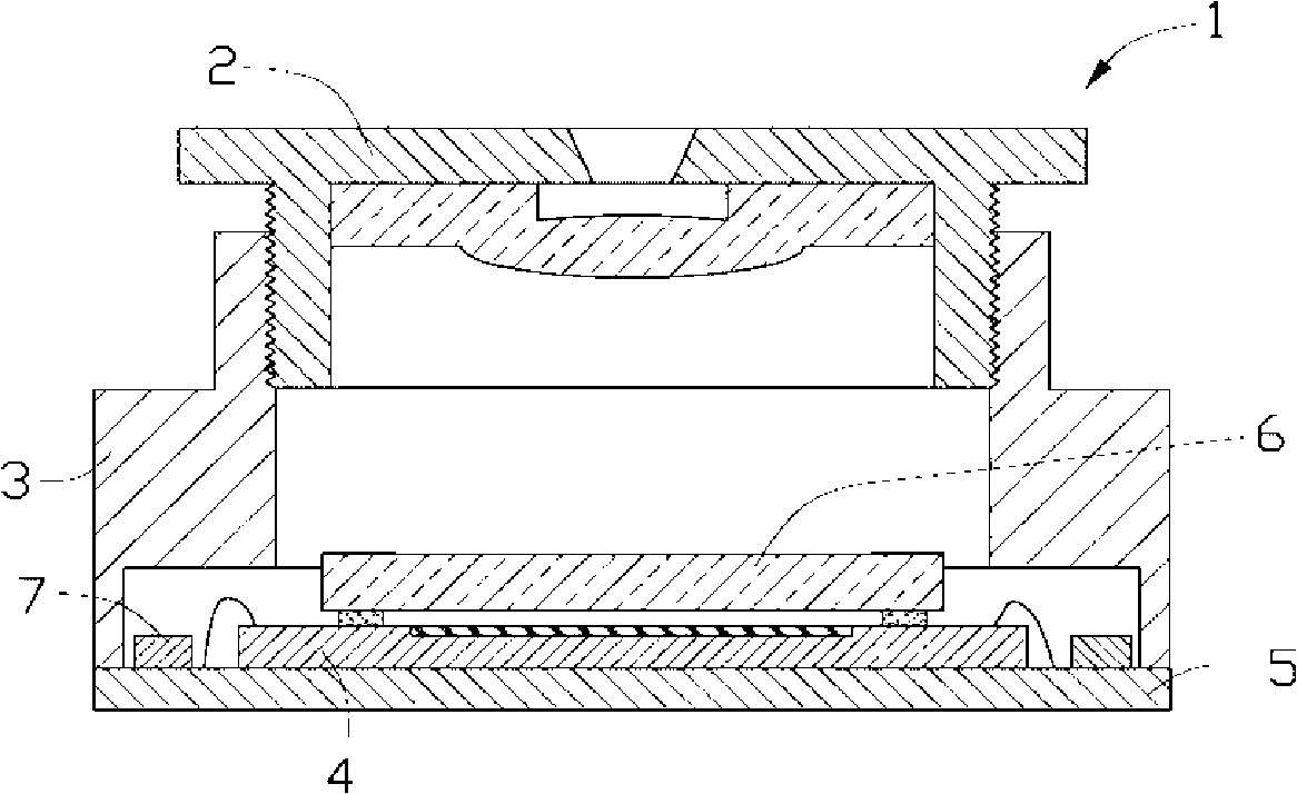
A camera module and chip technology, which is applied to printed circuits, installations, televisions, etc. where non-printed electrical components are connected, can solve the problems of reduced picture clarity, lack of electromagnetic protection measures for camera module 1, interference, and the like. Achieve the effect of being free from electromagnetic interference, improving clarity, and achieving electromagnetic shielding

Active Publication Date: 2009-02-04
FUJIN PRECISION IND JINCHENG CO LTD
View PDF0 Cites 17 Cited by
  • Summary
  • Abstract
  • Description
  • Claims
  • Application Information

AI Technical Summary

Problems solved by technology

[0003] In the camera module 1, when the electronic components of the passive components 7 are in operation, certain electromagnetic radiation will be generated, and since the camera module 1 doe

Method used


Image

  • Camera module
  • Camera module
  • Camera module

Examples


Embodiment Construction

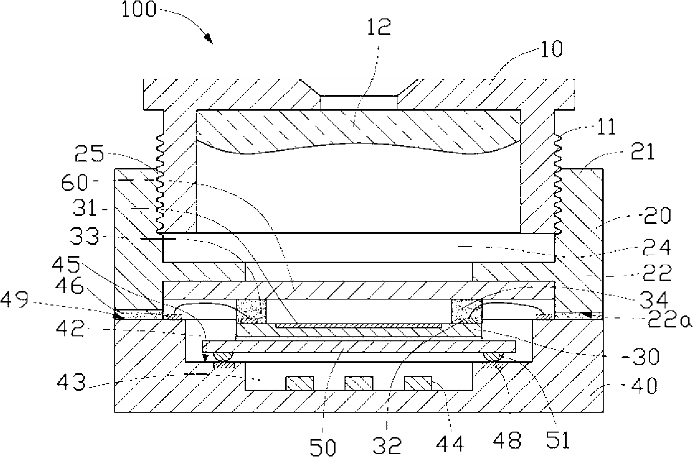
[0010] see figure 2 , is a cross-sectional view of the camera module 100 provided in the first embodiment of the present invention, which includes: a lens barrel 10 , a lens holder 20 , an image sensing chip 30 , and a substrate 40 . The mirror base 20 has a first end 21 and a second end 22 opposite to each other. The lens barrel 10 is sleeved on the first end 21 of the lens base 20 . The end surface 22 a of the second end 22 is bonded to the substrate 40 , and the image sensing chip 30 is fixed in the space enclosed by the mirror base 20 and the substrate 40 .

[0011] The outside of the lens barrel 10 has an external thread 11 and accommodates at least one lens 12 inside. The interior of the mirror base 20 is a penetrating chamber 24, and the side of the chamber 24 close to the first end 21 of the mirror base 20 is provided with an internal thread 25, which is compatible with the external thread of the lens barrel 10. 11 , so that the lens barrel 10 is sleeved on the len...


PUM


Abstract

The invention provides a camera module group, comprising a substrate, an image sensing wafer with a sensing area, a drawtube and a lens mount. The drawtube is sleeved at one end of the lens mount. The substrate is adhesively connected with the end face of the lens mount which is away from the drawtube. The surface of the substrate is provided with a first groove; and a second groove is arranged at the groove bottom of the first groove. At least an electronic element is housed on the second groove; and the groove bottom of the first groove is provided with at least a zero potential contact. A cover plate covering the second groove is arranged at the groove bottom of the first groove. The cover plate is electrically connected with the zero potential contact; and the image sensing wafer is adhesively connected on the cover plate and at the surface away from the second groove. The image sensing wafer is electrically connected with the substrate. A light penetration element, the image sensing wafer, the cover plate and the electronic element are housed in the space structured by the lens mount and the substrate. The camera module group achieves electromagnetic shielding, so that the image sensing wafer is free of electromagnetic interference.

Description

technical field [0001] The invention relates to a camera module, in particular to a camera module that can effectively prevent electromagnetic interference. Background technique [0002] see figure 1 , is a sectional view of a camera module 1 provided in the prior art, which includes a lens barrel 2 , a lens holder 3 and an image sensing chip 4 . The surface of the lens barrel 2 is provided with external threads. The mirror base 3 has a through chamber, and an internal thread is provided at one end of the inner wall of the mirror base 3 chamber. The external thread of the lens barrel 2 is engaged with the internal thread of the lens base 3 , so that the lens barrel 2 is sleeved on one end of the lens base 3 . A glass sheet 6 is bonded to the surface of the image sensing chip 4 for protecting the sensing area of ​​the image sensing chip 4 . The image sensing chip 4 is bonded on the surface of a substrate 5 , and its sensing area faces away from the substrate 5 . A passiv...

Claims


Application Information

Patent Timeline
IPC IPC(8): G02B7/02H05K1/18H05K9/00
CPCG02B7/023G02B13/001H04N5/2254H04N5/2257H04N5/2253H04N23/54H04N23/57H04N23/55
Inventor 林铭源
Owner FUJIN PRECISION IND JINCHENG CO LTD
Why Eureka
Try Eureka