
Light-collecting device for projection apparatus

A projection device and light-collecting technology, which is applied in projection devices, optics, optical components, etc., can solve the problems of high manufacturing difficulty, difficult manufacturing, and large light loss of light-collecting devices

Inactive Publication Date: 2009-02-04
DELTA ELECTRONICS INC
View PDF0 Cites 6 Cited by
  • Summary
  • Abstract
  • Description
  • Claims
  • Application Information

AI Technical Summary

Problems solved by technology

[0005] Because the structure of the aforementioned light collecting device is quite complicated, it is difficult to manufacture
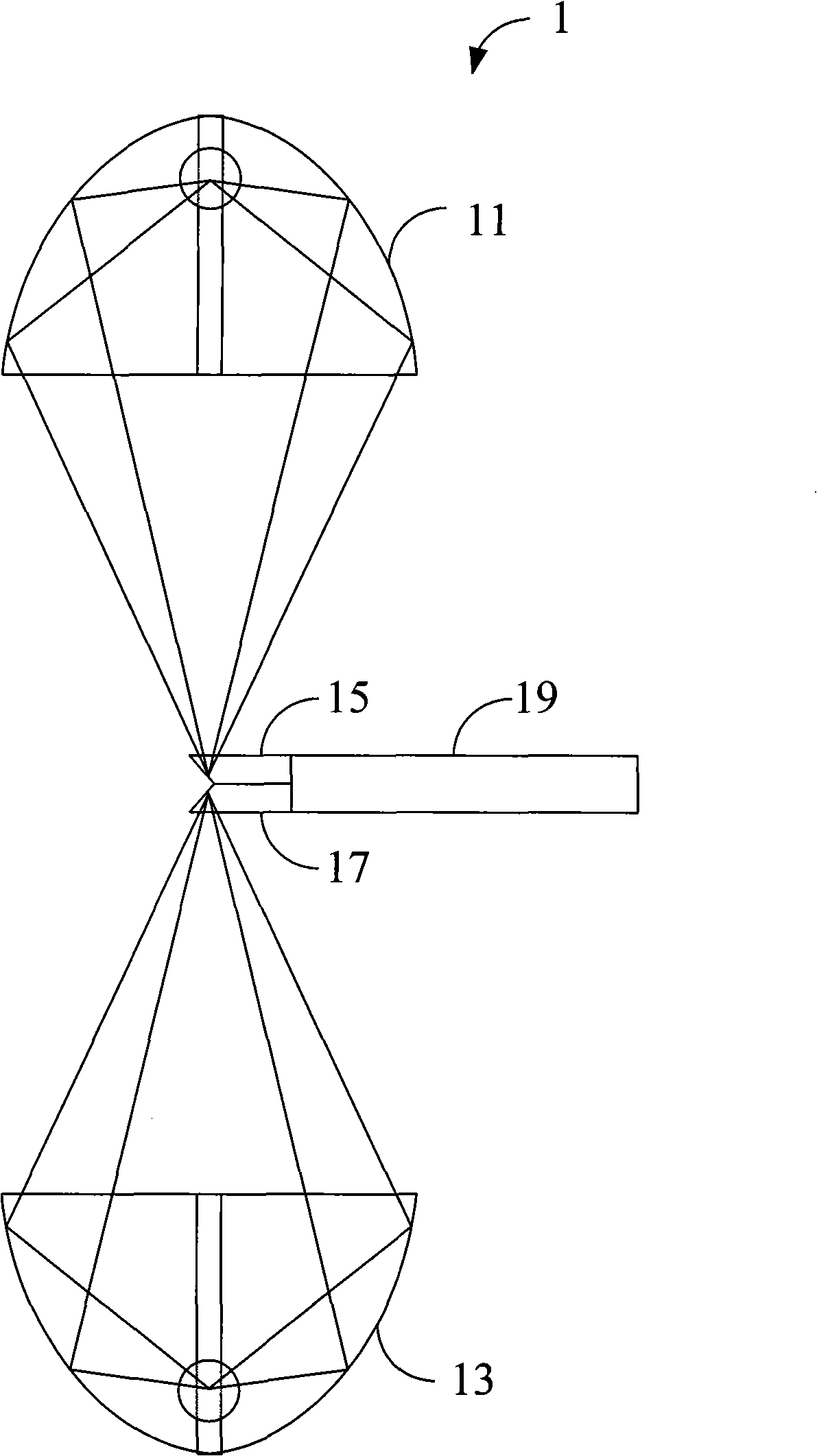
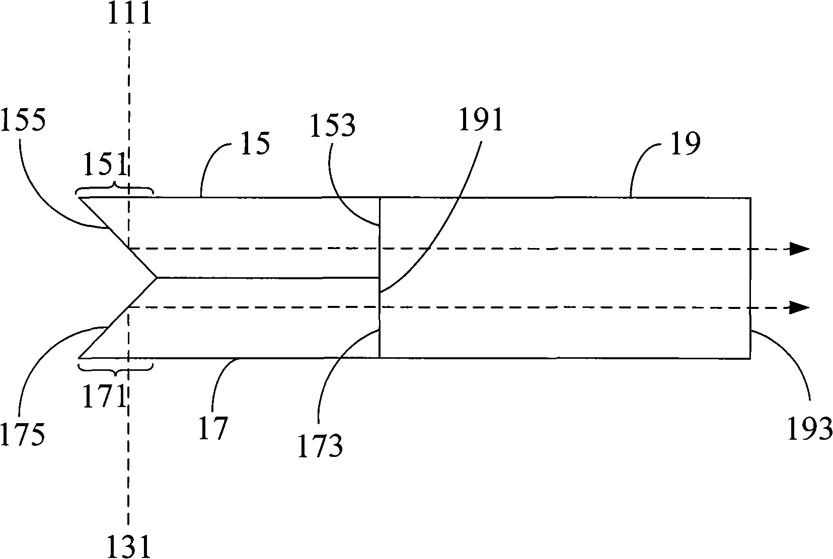
Specifically, because the structure of this light-collecting device is combined by three light-collecting columns, and each light-collecting column is extremely small in size, it is desired to combine the first light-collecting column 15 and the second light-collecting column 17 on the third light-collecting column 19 with certain technical difficulty
In addition, the coupling between light-collecting columns is not easy, the more times the optical path passes through the coupling part, the greater the optical loss will be
In addition, the areas of the reflective surfaces 155 and 175 are small, and it is very difficult to accurately coat the reflective materials.
[0006] On the other hand, because the aspect ratio of the digital micromirror device of the digital light processing projection system has a certain size ratio (usually 4:3, 16:9 or 16:10), if it is desired to make the light-emitting surface of the light-collecting column 193 is in line with the aspect ratio of the digital micromirror device, and considering the limitation of the light source itself, the projector must be installed as horizontally as possible; additional optical elements must be installed inside the projection device to correctly project light to the digital micromirror device. Not only increase the cost but also lead to more light loss
[0007] Moreover, the existing light-collecting device is only suitable for use with two light sources, and it is difficult to apply to a projection device with multiple light sources, and the application is less flexible.
[0008] To sum up, although the existing multi-light source lighting architecture can be used with two light sources, the light-collecting device has disadvantages such as high manufacturing difficulty and easy loss of coupled light.

Method used


Image

  • Light-collecting device for projection apparatus
  • Light-collecting device for projection apparatus
  • Light-collecting device for projection apparatus

Examples


Embodiment Construction

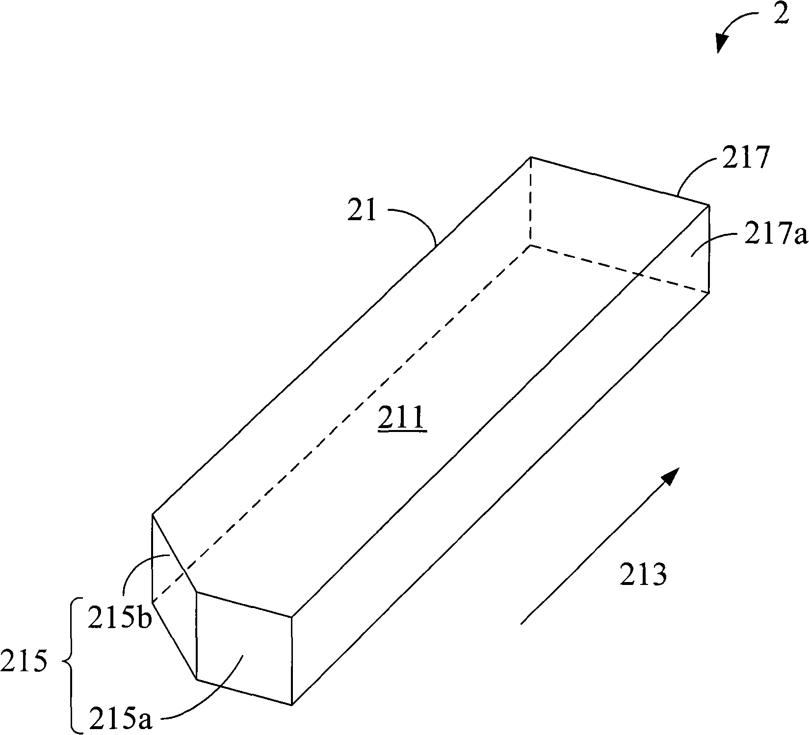
[0029] The present invention discloses a light collection device used in a projection device, in Figure 2A , 2B In the shown first embodiment, the projection device (not shown) includes a light collecting device 2, a first light source 20 and a second light source 22, wherein the perspective view of the light collecting device 2 is as Figure 2A As shown, the top view of the light collecting device 2 with the light source is as follows Figure 2B As shown, it should be noted that the drawings of the present invention illustrate the relationship between components, and are not intended to limit the size of each component. The light collecting device 2 includes a first light collecting rod 21 for collecting and homogenizing the light beams generated by the first light source 20 and the second light source 22 in the projection device. In addition, in this embodiment, both the first light source 20 and the second light source 22 are ultra high pressure mercury lamps (Ultra High...


PUM


Abstract

The invention provides a light gathering device for a projection device; the light gathering device at least comprises a light gathering column; and the light gathering column comprises a main body part, a vertical length direction, a light entry end part and a light exit end part. The light entry end part comprises an incidence surface and a reflection surface adjacent to the incidence surface; an angle is formed between the incidence surface and the reflection surface; the light exit end part is opposite to the light entry end part; wherein, a first ray can penetrate the incidence surface of the light entry end part to enter the main body part of the light gathering column, and then goes towards the light exit end part along the vertical length direction; and a second ray can enter the main body part of the light gathering column and is then reflected by the reflection surface of the light entry end part so as to go towards the light exit end part along the vertical length direction.

Description

technical field [0001] The present invention relates to a light collection device used in a projection device, in particular to a light collection device which is easy to manufacture and suitable for multi-light source projection devices. Background technique [0002] Generally speaking, a digital light processing (Digital Light Processing, DLP) projection system includes components such as a light source, a light splitting element, a light combining element, and a digital micromirror device (Digital Micromirror Device, DMD). After the light is processed by each component, it can be Generate an image. In a digital light processing projection system, in order to integrate the light and improve its uniformity, an integration rod is usually arranged on the light path behind the light source. After the light is emitted from the light source, it can enter the light-collecting column, and after multiple reflections inside the light-collecting column, it is emitted from the light-...

Claims


Application Information

Patent Timeline
Patent Type & Authority Applications(China)
IPC IPC(8): G03B21/14G02B27/10
Inventor 黄俊杰
Owner DELTA ELECTRONICS INC
Learn More