Driving mechanism and dough mixer

A technology of driving mechanism and driving parts, which is applied to the structural components of mixing/kneading machines, dough mixers, baking, etc. It can solve the problems of reducing the transmission effect of worms and gears, eccentricity, and large force, so as to reduce tooth collapse risk, ensure transmission efficiency, and improve bearing capacity

Pending Publication Date: 2019-08-02
BEAR ELECTRICAL APPLIANCE CO LTD
View PDF0 Cites 2 Cited by
  • Summary
  • Abstract
  • Description
  • Claims
  • Application Information

AI Technical Summary

Problems solved by technology

[0003] However, when the flour is stirred, the motor will work at high power or be blocked for a short time, which will cause uneven or too much force on the worm, which will easily cause eccentricity and even lead to tooth collapse, which

Method used


Image

  • Driving mechanism and dough mixer
  • Driving mechanism and dough mixer
  • Driving mechanism and dough mixer

Examples


Embodiment 1

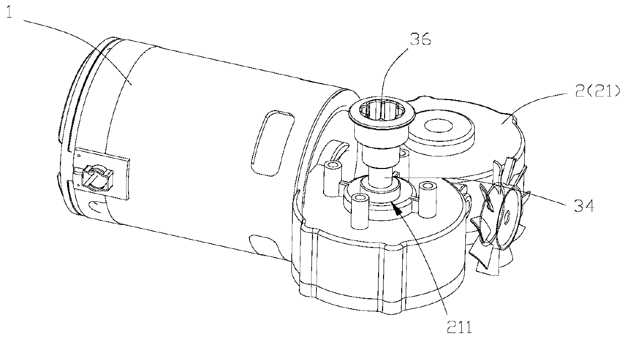
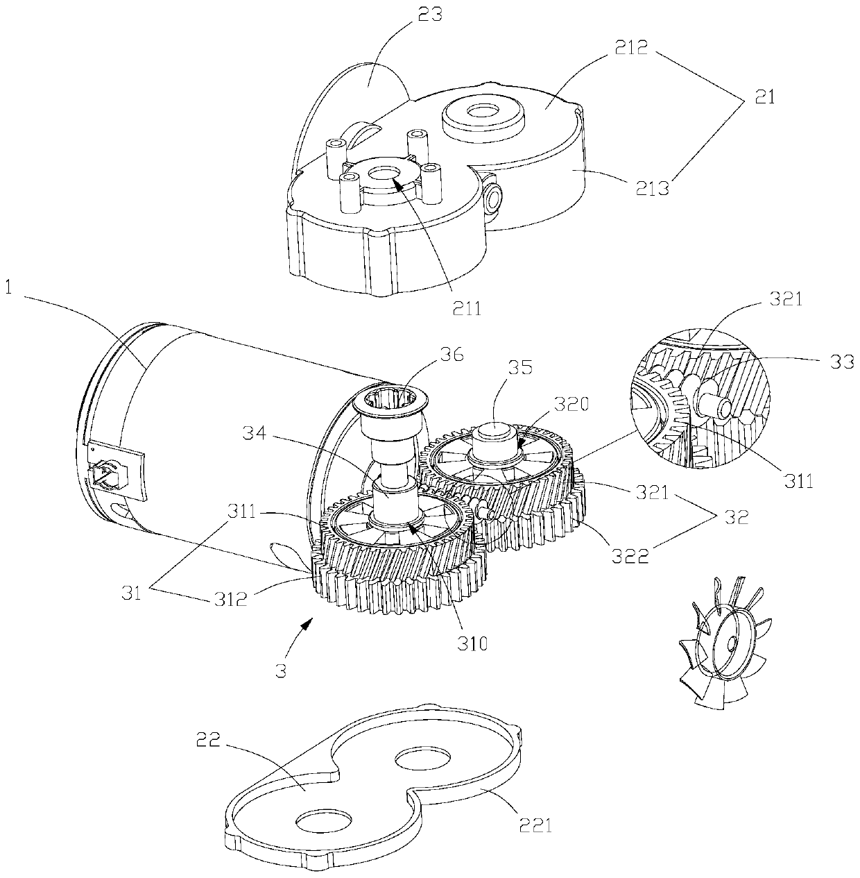
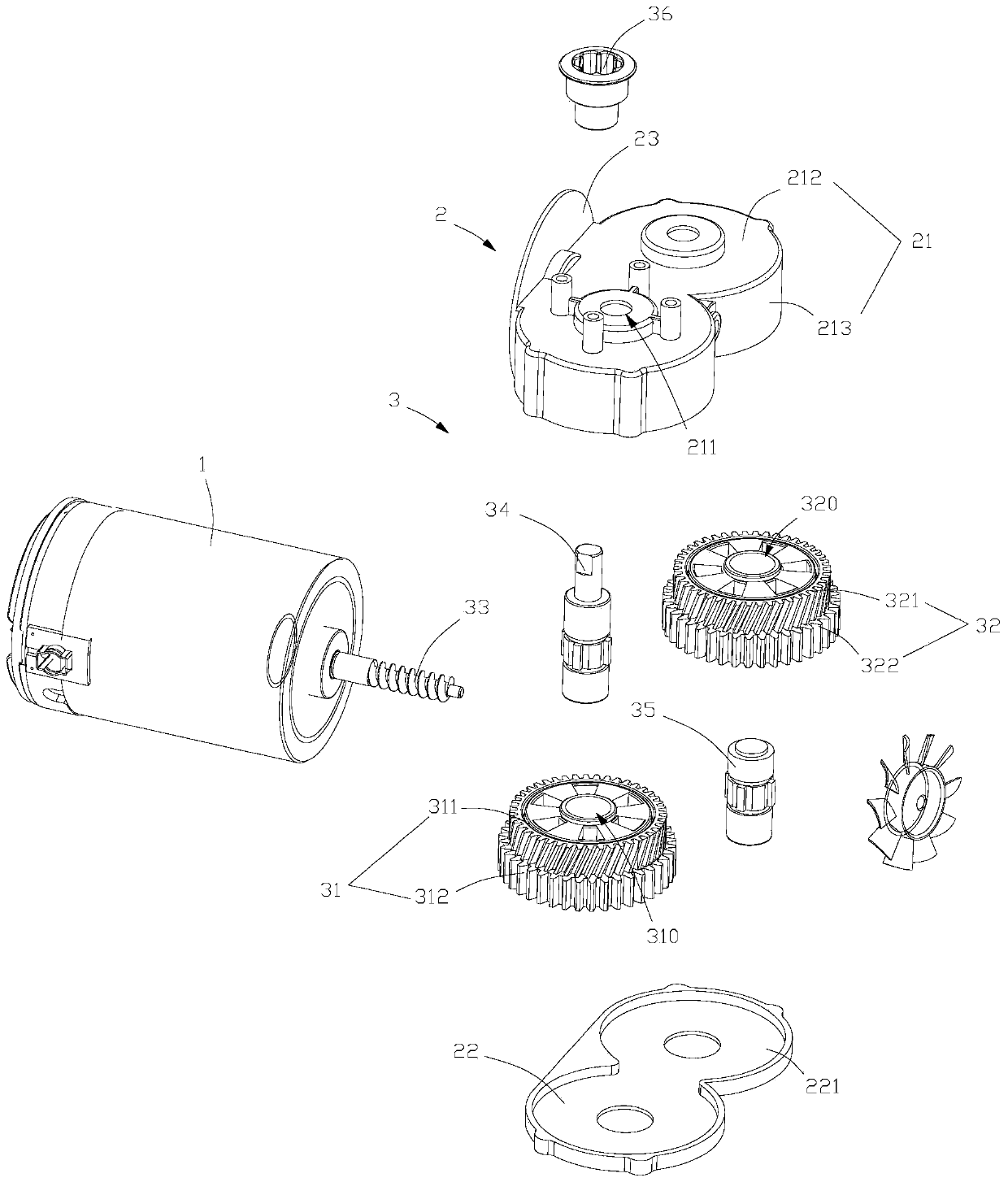
[0025] see Figure 1 to Figure 4 , the present embodiment provides a driving mechanism, including a motor 1, a fixed seat 2, a transmission assembly 3, a first key shaft 34, a second key shaft 35 and a driving member 36, and the transmission assembly 3 includes a worm 33, which is arranged on the The first duplex gear 31 and the second duplex gear 32 on the opposite sides of the worm 33, the worm 33 is driven to rotate by the motor 1, specifically, the side of the fixed seat 2 is provided with a 33 is inserted into the assembly hole of its inner cavity (not shown in the assembly hole figure), the worm 33 is installed in the holder 2 through the assembly hole, and the first dual gear 31 and the second dual gear 32 can be It is rotatably installed on both sides of the inner cavity of the fixed seat 2, and the package of the first double gear 31 and the second double gear 32 is facilitated by setting the fixed seat 2, thereby improving the integrity and compactness of the equipme...

Embodiment 2

[0035] see Figure 1 to Figure 6 , this embodiment provides a dough mixer using the driving mechanism 30 of the first embodiment, which includes a base 10 and a pot body 20, the pot body 20 is arranged on the upper side of the base 10, and the driving mechanism of the first embodiment is arranged inside the base 10 30, the bottom of the pot body 20 is provided with a stirring member (the stirring member is not shown in the figure), the upper side of the base 10 is provided with a gap 101 corresponding to the driving member 36, and the driving member 36 passes through the gap 101 and The stirring parts are connected, and since the dough mixer adopts the drive mechanism 30 of the present invention, it not only reduces the risk of chipping, but also ensures that once the main output gear 311 chipping occurs, the equipment can continue to operate, thereby improving User experience.

[0036] see Figure 1 to Figure 6 , the motor 1 is horizontally placed in the base 10 along its a...


PUM


Abstract

The invention belongs to the technical field of kitchen appliances, and particularly relates to a driving mechanism and a dough mixer. The driving mechanism comprises a motor, a transmission assemblyand a driving piece; the transmission assembly comprises a worm, a first duplicate gear and a second duplicate gear which are arranged at two opposite sides of the worm, the worm is driven to rotate by the motor, the first duplicate gear comprises a primary output gear and a secondary output gear which are concentrically arranged, the primary output gear is meshed with the worm; the second duplicate gear comprises a primary transmission gear and a secondary transmission gear which are concentrically arranged, the primary transmission gear is meshed with the worm, the secondary output gear is meshed with the secondary transmission gear; the first duplicate gear is connected with the driving piece, the driving piece is used for connecting a stirring piece of a stirring device. By adopting the driving mechanism provided by the invention, not only is the teeth cracking risk reduced, but also that the equipment can be ensured to continuously run once the primary output gear has occurred teeth cracking.

Description

technical field [0001] The invention belongs to the technical field of kitchen appliances, in particular to a driving mechanism and a dough mixing machine. Background technique [0002] Existing horizontal noodle kneading machines generally include a base and a pot body. The base is provided with a driving mechanism. The driving part connected by the transmission of the agitator, the existing transmission mechanism usually includes a motor and a helical gear, the output shaft of the motor is connected with a worm, the helical gear and the worm mesh, the above-mentioned driving part is connected with the helical gear, and the motor controls the rotation of the worm Drive the helical gear to rotate, so that the driving part drives the stirring part to rotate and stir the flour in the pot body, so as to realize the function of kneading noodles. [0003] However, when the flour is stirred, the motor will work at high power or be blocked for a short time, which will cause uneven...

Claims


Application Information

Patent Timeline
IPC IPC(8): A21C1/14
CPCA21C1/1465
Inventor 李一峰刘国庆刘睦林
Owner BEAR ELECTRICAL APPLIANCE CO LTD
Why Eureka
Try Eureka