
Illuminating device

A technology for lighting devices and lighting modules, which is applied in the direction of lighting devices, lighting devices, lighting device components, etc., can solve the problems of affecting the strength of light poles and messy wiring, so as to improve user experience, improve installation cleanliness, and optimize The effect of lighting fixtures

Inactive Publication Date: 2017-09-15
山东中微光电子有限公司
View PDF5 Cites 1 Cited by
  • Summary
  • Abstract
  • Description
  • Claims
  • Application Information

AI Technical Summary

Problems solved by technology

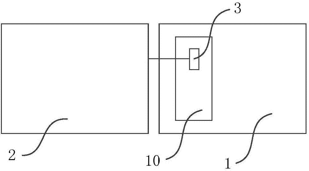
[0004] The embodiment of the present invention provides a lighting device to solve the problems of messy wiring caused by the installation of the micro base station on the outside of the light pole or the impact of perforated installation on the strength of the light pole. While increasing the coverage of the micro base station, the lighting device can be realized tidy installation

Method used


Image

  • Illuminating device
  • Illuminating device
  • Illuminating device

Examples


Embodiment Construction

[0026] The present invention will be further described in detail below in conjunction with the accompanying drawings and embodiments. It should be understood that the specific embodiments described here are only used to explain the present invention, but not to limit the present invention. In addition, it should be noted that, for the convenience of description, only some structures related to the present invention are shown in the drawings but not all structures.

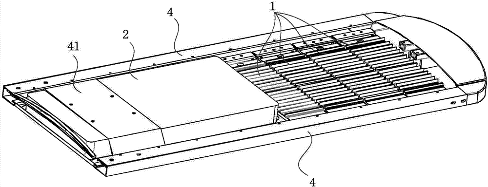
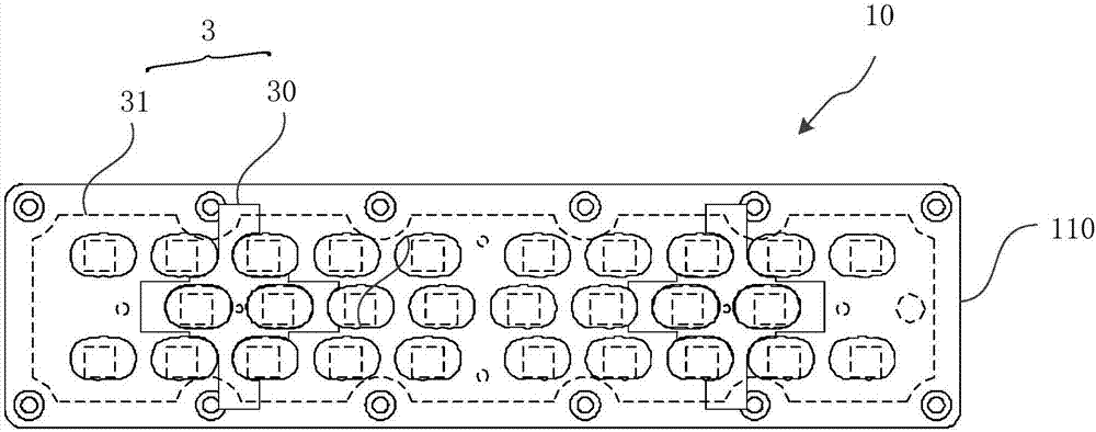
[0027] figure 1 It is a schematic structural diagram of an illuminating device provided by Embodiment 1 of the present invention. Such as figure 1 As shown, the lighting device provided by the embodiment of the present invention includes: a lighting module 1, a micro base station module 2 and at least one group of micro base station antennas 3; wherein, the lighting module 1 includes at least one group of light source modules 10, and the micro base station antenna 3 is arranged on The light source module 10 is i...


PUM


Abstract

The invention discloses an illuminating device and relates to the technical field of illumination and communication. The illuminating device comprises an illuminating module, a micro base station module and at least one group of micro base station antennae; the illuminating module comprises at least one group of light source modules; and the micro base station antennae are arranged in the light source modules and are connected with the micro base station module through feeders. According to the technical scheme, the micro base station module is integrated in the illuminating device, so that the illuminating function can be realized, and the communication function can also be realized; besides, the micro base station antennae are arranged in the light source modules of the illuminating device, thus the internal space of the light source modules can be utilized effectively, and the internal space of the illuminating device is not required to be increased separately; besides, the internal wiring manner is adopted, the problems of disordered wiring, unattractiveness, influence on the strength of a lamp pole and the like due to the fact that the micro base station antennae are mounted outside the lamp pole can be effectively solved, an existing illuminating device is optimized, the space is saved, the mounting tidiness of the illuminating device is improved, and the user experience is improved.

Description

technical field [0001] Embodiments of the present invention relate to the technical field of illumination and communication, and in particular, to an illumination device. Background technique [0002] The current communication base stations are basically erected on the top of iron towers or buildings, and are generally called macro base stations. With the rapid development of the mobile Internet, the existing macro base stations cannot fully meet the requirements in terms of capacity and quality in the coverage area. Capacity expansion is generally achieved by increasing frequency points or reducing the radius of the cell, but the number of frequency points is limited, and the only way to increase user capacity and signal quality is to reduce the radius of the cell, that is, to use micro base stations for coverage. [0003] Due to the reduction of the radius of the cell, more micro base stations are needed, and due to the rapid development of society, it is becoming more and...

Claims


Application Information

Patent Timeline
IPC IPC(8): F21V33/00
CPCF21V33/00
Inventor 孔瑞
Owner 山东中微光电子有限公司
Learn More