Check patentability & draft patents in minutes with Patsnap Eureka AI!

LCD drive g device and drive method

A technology of liquid crystal drive and liquid crystal display panel, which can be used in instruments, static indicators, etc., and can solve problems such as inconvenience

Active Publication Date: 2012-09-05
MEDIATEK INC
View PDF0 Cites 0 Cited by
  • Summary
  • Abstract
  • Description
  • Claims
  • Application Information

AI Technical Summary

Problems solved by technology

[0004] Generally speaking, the display speed of the liquid crystal display panel has a common standard, for example: 60 pictures per second, so the driving circuit of the liquid crystal display panel must charge the voltage of the storage capacitor Cs and the liquid crystal capacitor Clc to a predetermined value within a certain period of time However, LCD pixels of different sizes have different capacitance and resistance values. In the formula iΔt=cΔV, i is the current value, Δt is the charging time, c is the capacitance value, and ΔV is the voltage difference value, if the ΔV required by the storage capacitor Cs of the display unit and the liquid crystal capacitor Clc is constant, and the capacitance c of different sizes of liquid crystal display panels is different, but because the display speed is fixed (that is, the charging time Δt is fixed), Therefore, the charging current can only be corrected to meet the needs of the liquid crystal display panel, so that the voltage of the display unit can be charged to a predetermined value within a fixed time.
[0005] However, the driving force (that is, the magnitude of the charging current) of the existing liquid crystal display panel driving device has been pre-set for a specific liquid crystal display panel before manufacture, which means that the driving device can only be used for a specific liquid crystal display panel. It is quite inconvenient to prepare different driving devices for the liquid crystal display panel. For this reason, the present invention proposes a solution here

Method used


Image

  • LCD drive g device and drive method
  • LCD drive g device and drive method
  • LCD drive g device and drive method

Examples


Embodiment Construction

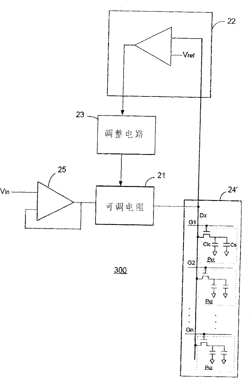
[0015] figure 2 Shown is a schematic diagram of modules of the liquid crystal driving device of the present invention. As shown in the figure, the liquid crystal driving device 200 of the present invention includes an adjustable resistor 21 , a comparing unit 22 , and an adjusting unit 23 . The adjustable resistor 21 receives an input voltage V in After that, output an output current I out to the data line of the liquid crystal display panel 24, wherein the output current I out It is used to charge the display unit on the liquid crystal display panel 24 , that is to charge the storage capacitor and the liquid crystal capacitor of the display unit. The comparison unit 22 is coupled to a data line of the liquid crystal display panel 22 for receiving a voltage of a display unit on the data line and comparing it with a predetermined reference voltage V ref performing a comparison to generate a comparison result. The adjustment unit 23 adjusts the resistance value of the adjus...


PUM


Abstract

The invention aims to provide a liquid crystal drive device which can automatically adjust the drive force according the panel adopted by the drive device. The invention provides a liquid crystal drive device which can automatically adjust the drive force. The drive device comprises an adjustable resistor coupled with a data line of the liquid crystal display panel and used for receiving an inputvoltage and outputting an output current to the data line of the liquid crystal display panel; a comparing unit is coupled with a data line of the liquid crystal display panel and used for receiving the voltage of a display unit of the data line and comparing the voltage with the preset voltage to generate a result; an adjusting unit is used for adjusting the adjustable resistor according to the comparison result, so as to regulate the magnitude of the current.

Description

technical field [0001] The invention relates to a liquid crystal driving device and a driving method Background technique [0002] figure 1 Shown is a schematic diagram of an equivalent circuit of an existing liquid crystal display panel and its driving circuit. As shown in the figure, the liquid crystal display panel module 100 is formed by criss-crossing data lines (D1-Dm) and gate lines (G1-Gn), wherein the data voltage of the data lines is provided by a source driver 11, The scanning voltage of the gate line is provided by a gate driver 12, and each set of interleaved data lines and gate lines is used to control a display unit P, and the equivalent circuit of each display unit P includes a thin film electric circuit Crystal, a storage capacitor Cs and a liquid crystal capacitor Clc, the gate and source of the thin film transistor are respectively connected to the gate line (G1-Gn) and the data line (D1-Dm), and its drain is connected to the storage capacitor Cs . [...

Claims


Application Information

Patent Timeline
Patent Type & Authority Patents(China)
IPC IPC(8): G09G3/36G09G3/20G02F1/133
Inventor 王建全
Owner MEDIATEK INC
Features
  • R&D
  • Intellectual Property
  • Life Sciences
  • Materials
  • Tech Scout
  • Unparalleled Data Quality
  • Higher Quality Content
  • 60% Fewer Hallucinations
Learn More