
Modular parallel great power DC power source switch apparatus

A technology of DC switch and power supply device, which is applied in the conversion device of output power, the conversion of DC power input to DC power output, electrical components, etc. problems, to achieve the effect of improving stability, reducing costs, and being easy to use

Active Publication Date: 2009-02-04
XIAN ACTIONPOWER ELECTRIC
View PDF0 Cites 16 Cited by
  • Summary
  • Abstract
  • Description
  • Claims
  • Application Information

AI Technical Summary

Problems solved by technology

The disadvantages of this parallel connection method are: First, the master and slave settings need to be set before each use, which increases the number of operations
The second is that if the main module fails, the entire power supply device cannot work, and it is difficult to improve the reliability of the work.
The third is that the output stability is not high enough. This is because the device only performs negative feedback control of the shunt output current, but does not perform negative feedback control of the total output current. That is to say, only one is set at the output of each module. Current feedback detection point, and use the current negative feedback inner loop of each module to carry out negative feedback control of the shunt current in the module, but there is no feedback current detection point at the total output end after multiple modules are connected in parallel, and there is no total output The current negative feedback control loop, therefore, the negative feedback control of the total output current cannot be performed
Because in the parallel device, the current has a process of shunting and then merging, if only the negative feedback control of shunting is performed, and the negative feedback control after merging is not performed, it is difficult to achieve a good level of output stability.

Method used


Image

  • Modular parallel great power DC power source switch apparatus
  • Modular parallel great power DC power source switch apparatus
  • Modular parallel great power DC power source switch apparatus

Examples


Embodiment Construction

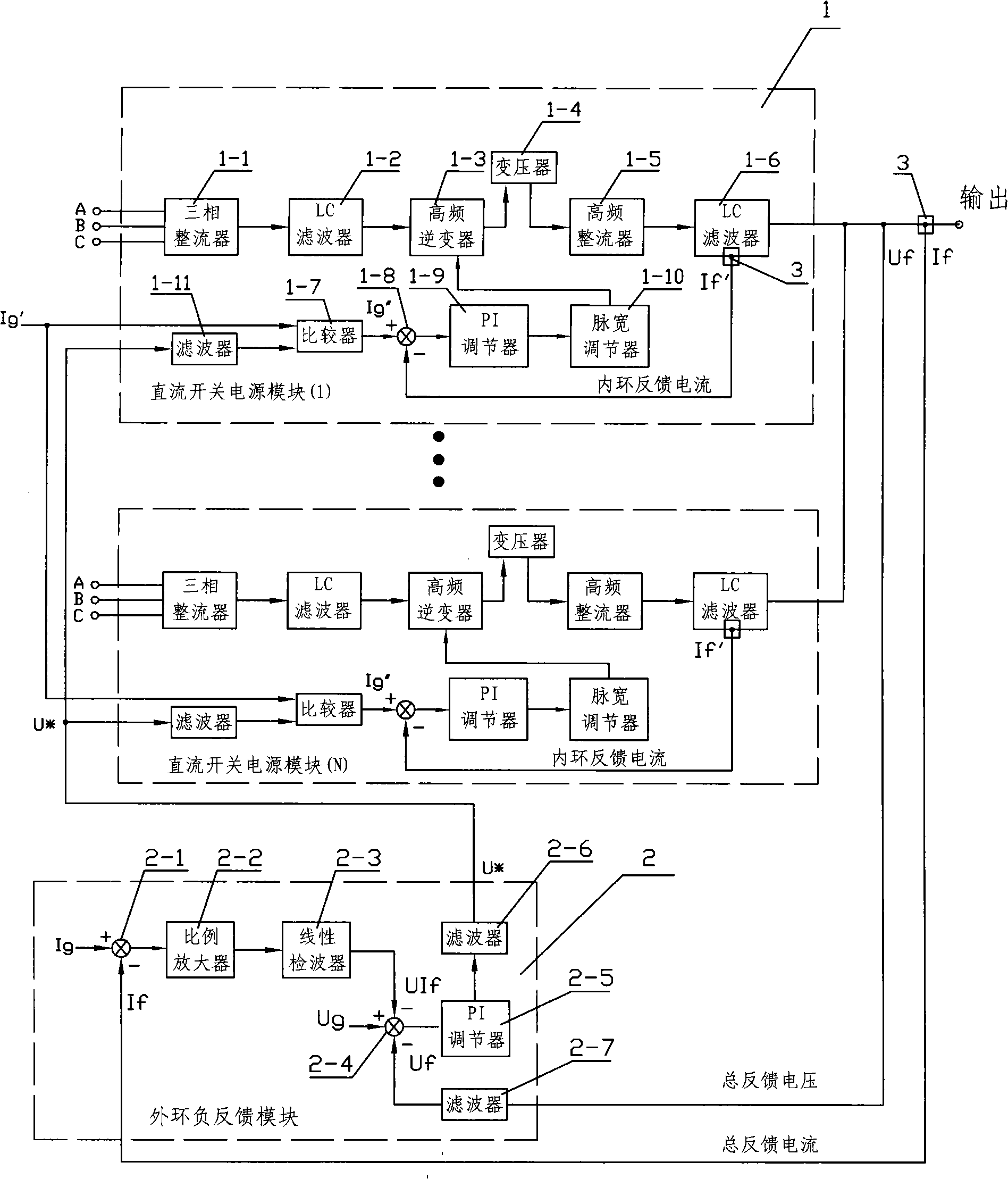
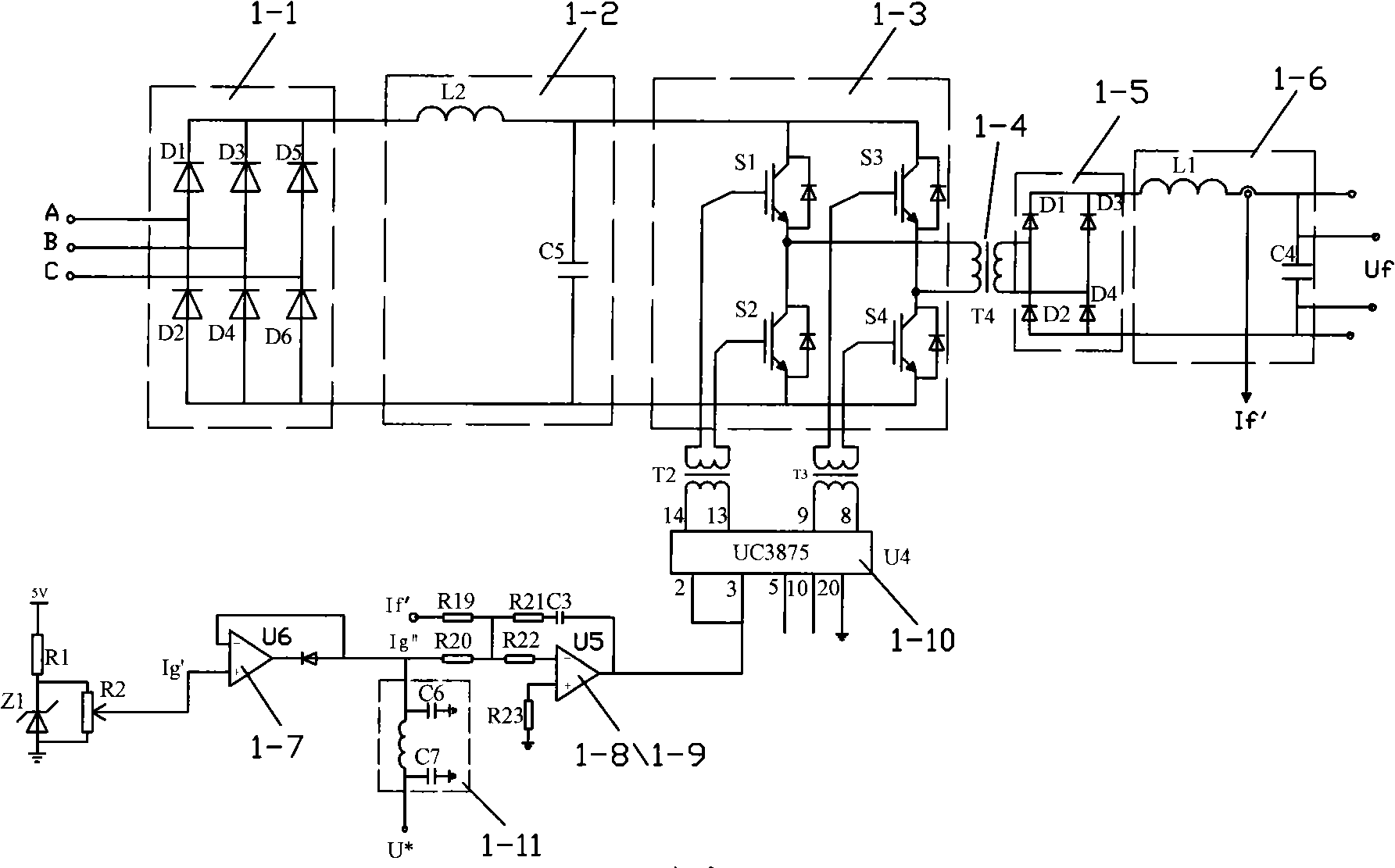
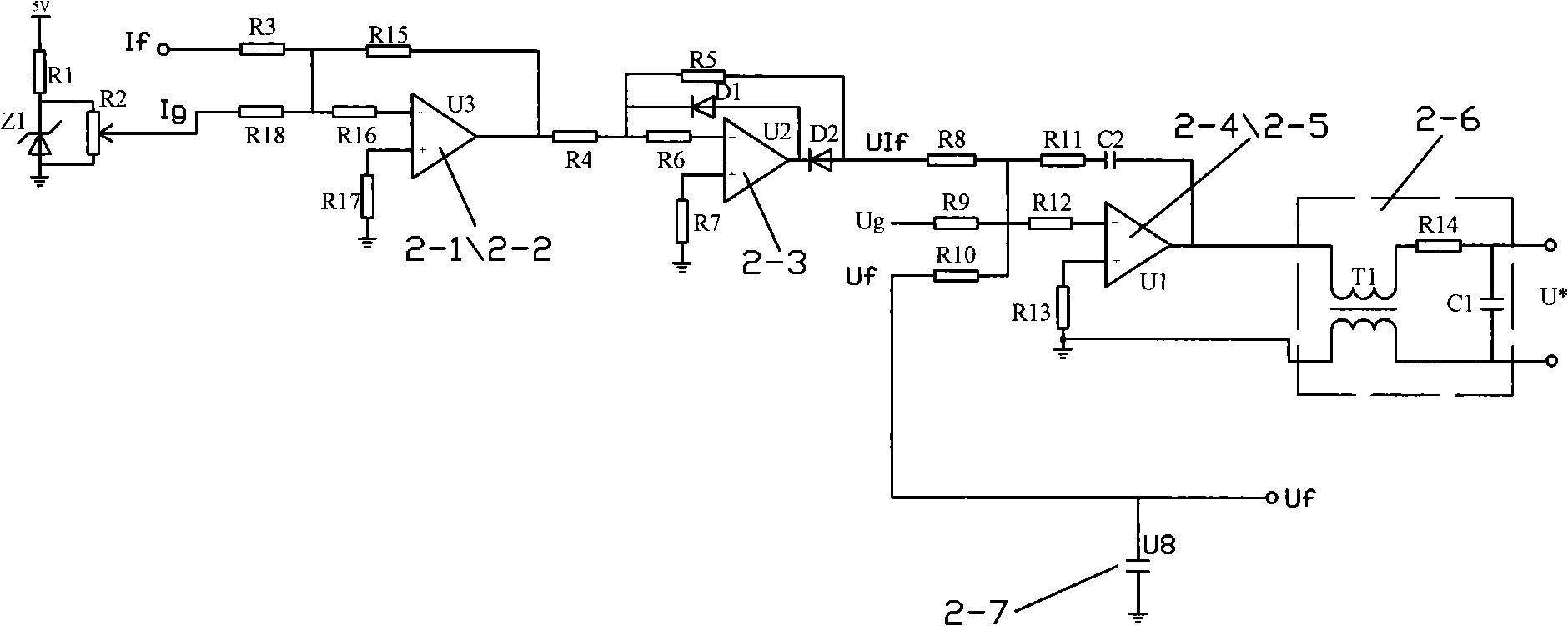
[0016] see figure 1 , 2 , the DC switching power supply module 1 has an AC-DC-AC-DC conversion main loop, which is mainly composed of a three-phase AC rectifier 1-1, an input LC filter 1-2, a high-frequency inverter 1-3, output transformer 1-4, high-frequency rectifier 1-5 and output LC filter 1-6 are connected to form, module 1 has a current negative feedback inner loop, which is composed of comparator 1-7, the first The three subtractors 1-8, the second voltage regulator 1-9 and the pulse width regulator 1-10 are connected to form. Among them, the comparator 1-7 is a comparison detector connected by the operational amplifier U6, which completes the output of the given current Ig' and the total feedback callback value U of this module. * The comparison of the lower one is selected as the actual given value Ig of this module at the same time; the third subtractor 1-8 and the second voltage regulator 1-9 are composed of operational amplifier U5 and resistance and capacitance...


PUM


Abstract

The invention relates to a module parallel type high power direct current switch power device which comprises a plurality of direct current switch power modules which are parallel and a plurality of outer ring negative feedback modules of total output current and voltage after being parallel. One of the direct current switch power modules is internally provided with a current negative feedback inner ring control loop, and one of the outer ring negative feedback modules is internally provided with a total output current negative feedback outer loop and a total output voltage outer ring loop. The invention eliminates the master-slave installation operation of the prior master-slave installation method parallel power device, thereby causing the use to become simple, saving components and lowering the cost. At the same time, the device is added with the total output current negative feedback outer ring loop to cause the total output current after being parallel to also get negative feedback control, thereby greatly enhancing the output stability of the device.

Description

technical field [0001] The invention relates to a high-power direct current switching power supply, in particular, it is a module parallel high-power direct current switching power supply device. Background technique [0002] DC switching power supply is a new type of power conversion device that has emerged in recent years. Its working method is AC-DC-AC-DC, that is, it first rectifies and filters the 50Hz low-frequency AC of the power grid into DC, then inverts the DC into high-frequency AC, and then rectifies and filters the high-frequency AC into DC output. Among them, the transformation efficiency of high-frequency AC in the transformer is much higher than that of 50Hz low-frequency grid AC. Therefore, the transformer can be made very small. Therefore, compared with the traditional phase-controlled power supply, it has the advantages of small size and light weight, so it has been developed in recent years. However, because it is limited by the rated power of power dev...

Claims


Application Information

Patent Timeline
IPC IPC(8): H02M3/28H02M3/335
Inventor 田学武石勇岳艳伟吴泉兵
Owner XIAN ACTIONPOWER ELECTRIC
Learn More