

Motor synchronous control system of sponge cutting machine
A sponge cutting machine and synchronous control technology, applied in the direction of controlling multiple AC motors, multiple motor speed adjustments, etc., can solve the mechanical part damage of the equipment, the knife is easy to be broken, and affect the stability and service life of electromechanical equipment, etc. problems, to achieve the effect of prolonging stability and service life
- Summary
- Abstract
- Description
- Claims
- Application Information
AI Technical Summary
Problems solved by technology
Method used
Image

Examples
Embodiment Construction
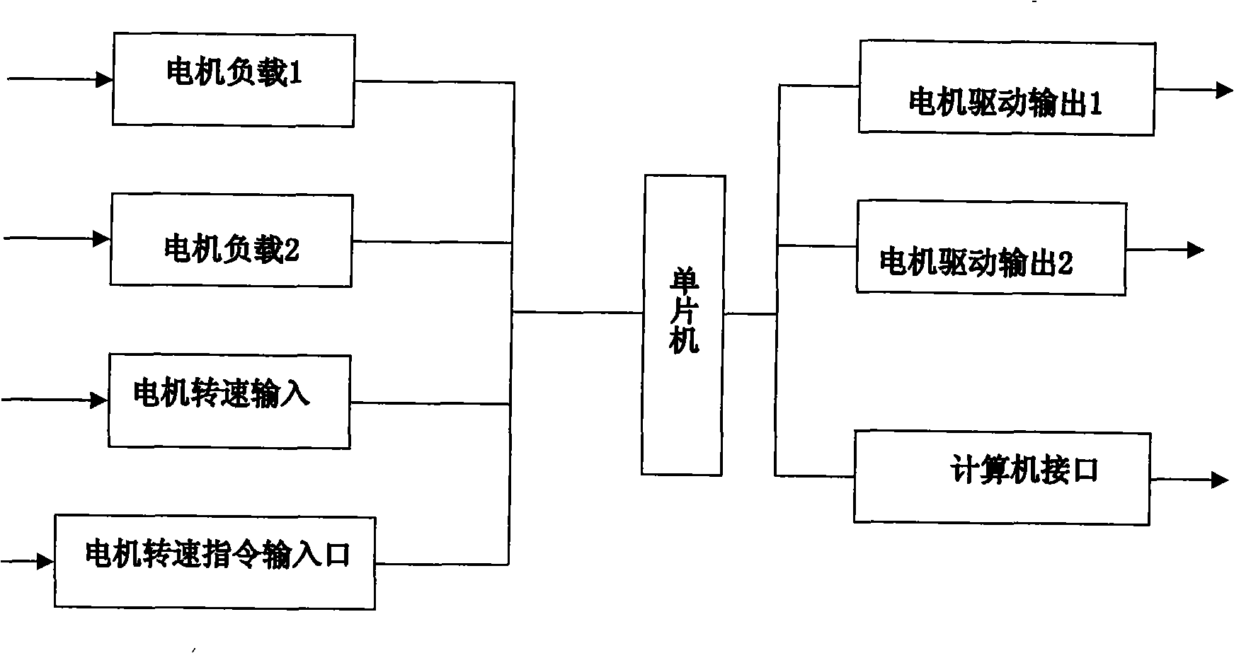
[0017] Such as figure 1 As shown, the input terminal 1 of the servo motor synchronous control card is the load input of the servo motor A, the input terminal 2 is the load input terminal of the servo motor B, the input terminal 3 is the speed input of the servo motor, and the input terminal 4 is the speed command input port of the servo motor , the output end 5 is the drive output of the servo motor A, the output end 6 is the drive output of the servo motor B, and the output end 7 is the computer interface.
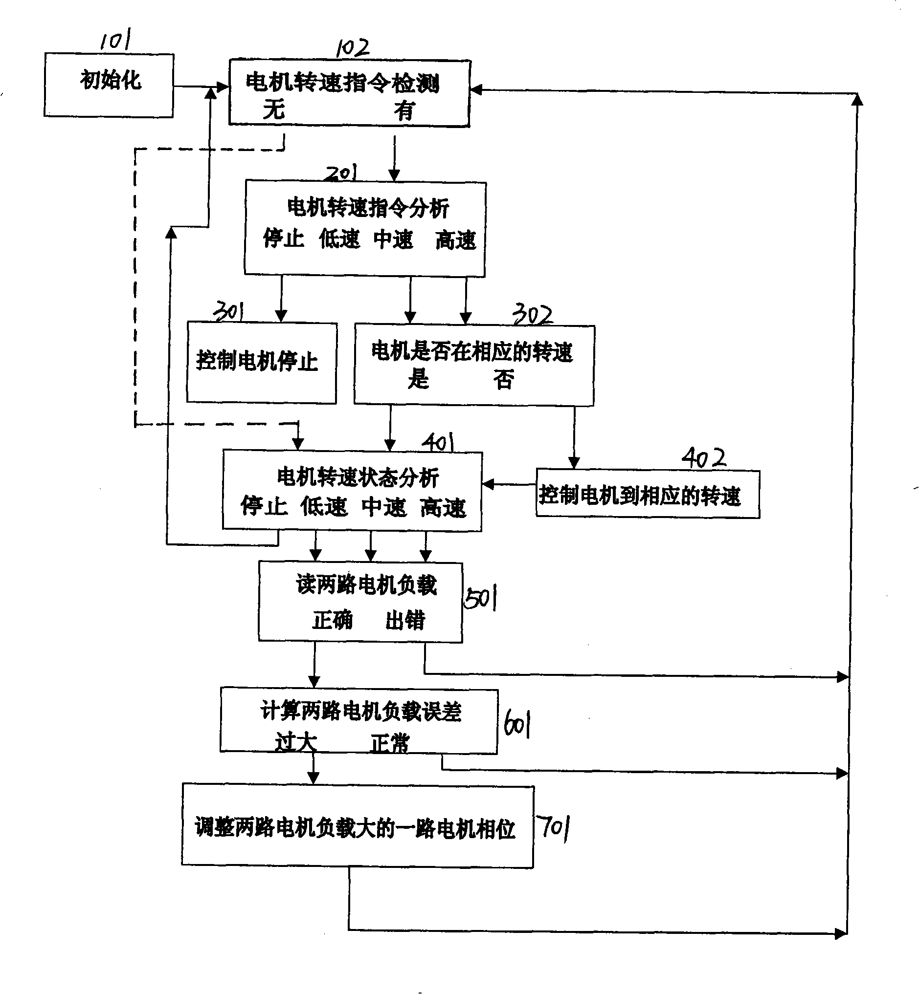
[0018] figure 2 Shown is the program block diagram of the servo motor synchronous control system, step 101: first initialize, and assign appropriate initial values to the relevant storage units. Step 102: Detect the motor speed instruction, if the motor speed is detected, go to step 201, if not, go to step 401.
[0019] Step 201, analyze the motor speed instruction, if it is analyzed that it is a stop instruction, stop by controlling the motor, step 301 returns to st...
PUM
 Abstract
Description
Claims
Application Information