Cleaning apparatus

A cleaning machine and cleaning liquid technology, applied in the field of cleaning machines, can solve the problems of increased enterprise cost, short cleaning time, poor cleaning effect, etc., and achieve the effect of improving work efficiency, improving cleaning quality and good cleaning effect

Inactive Publication Date: 2009-02-11
SHENGRUI TRANSMISSION
View PDF0 Cites 37 Cited by
  • Summary
  • Abstract
  • Description
  • Claims
  • Application Information

AI Technical Summary

Problems solved by technology

[0002] The piston pin is one of the parts of the diesel engine, which requires high mechanical properties such as surface hardness. In order to meet the use requirements, the piston pin usually needs to be heat treated. After quenching during the heat treatment process, it usually needs to be tempered. The pin is covered with quenching oil. In order to avoid the generation of smoke during tempering, it is usually cleaned before tempering; piston pins are produced in large quantities, and the number of cleaning is large. Usually, multiple parts are cleaned at one time. High-pressure spraying method is used for cleaning. Due to the large amount of cleaning at one time and the short cleaning time, it is easy to produce dead angles of spraying, which makes the cleaning of various parts uneven, the cleaning effect is not good, and the cleaning requirements cannot be met.
There are usually two ways to transport workpieces to the washing machine, one is manual transport, and the other is machine transport. Manual transport has low efficiency and slow rhythm, wastes manpower and material resources, and increases enterprise costs; while machine transport generally adopts conveyor belt transmission. , and the transmission belt transmission has its own weaknesses, it will be difficult to meet the requirements of use

Method used


Image

  • Cleaning apparatus
  • Cleaning apparatus
  • Cleaning apparatus

Examples


Embodiment Construction

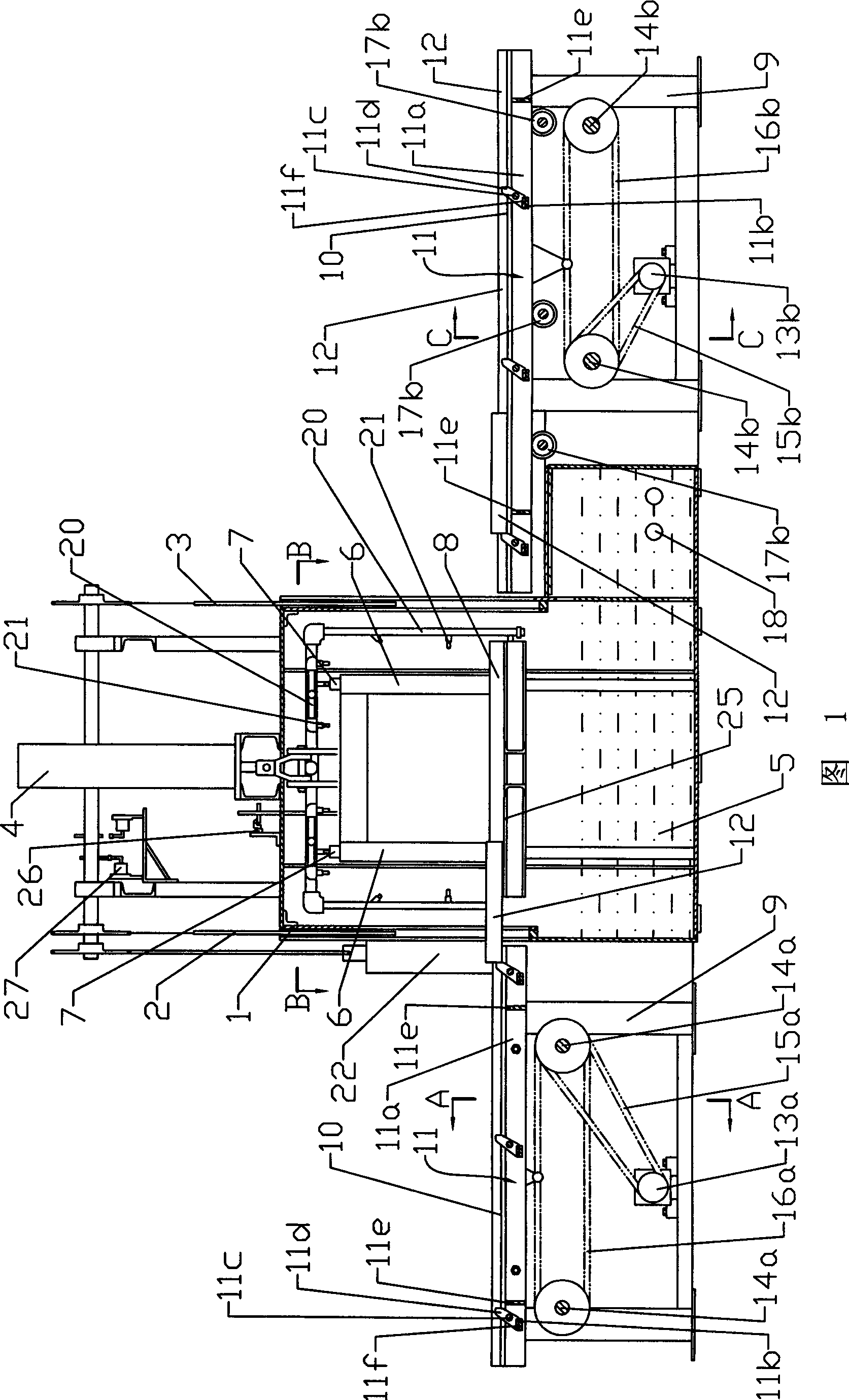
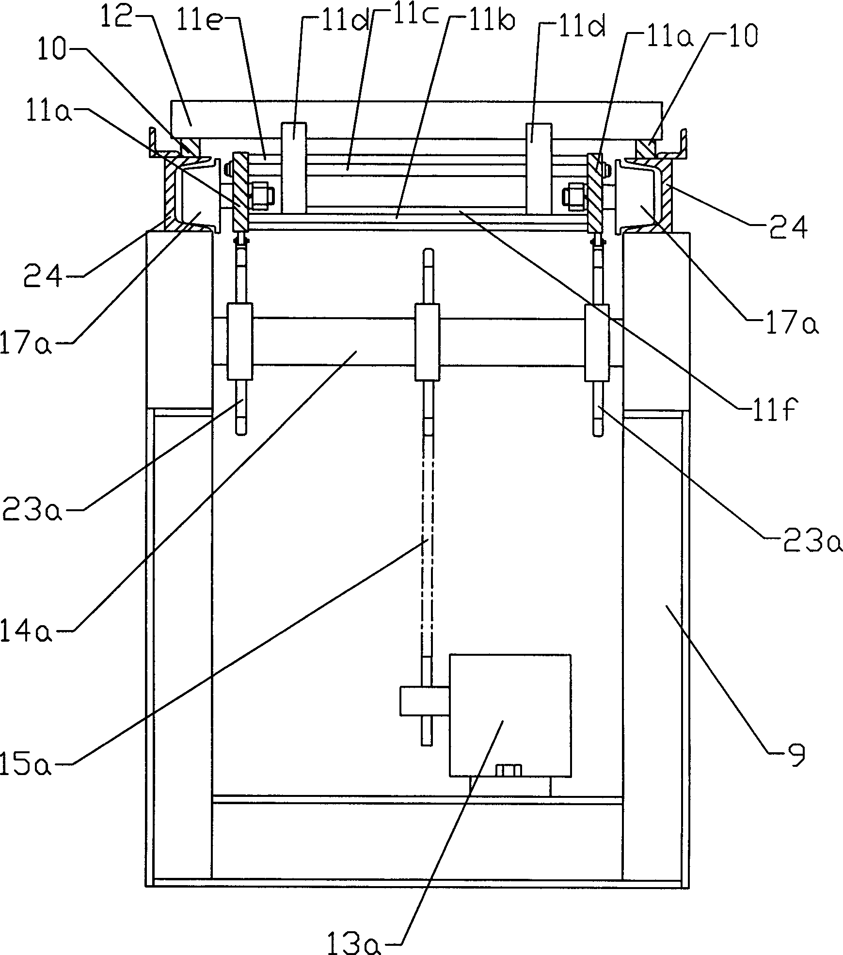
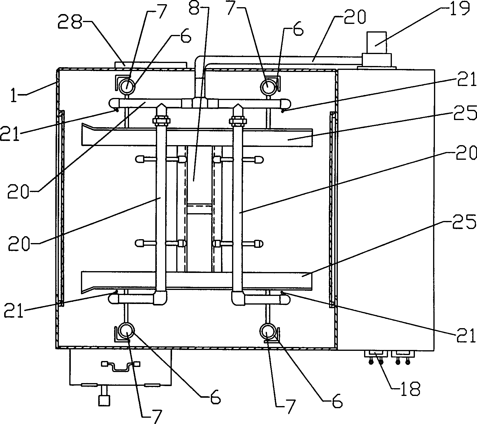
[0019] Figure 1, image 3 As shown, a cleaning machine includes a transmission device and a cleaning device. The cleaning device includes a housing 1, and the two sides of the housing 1 are provided with a feed door 2 and a discharge door 3, and the feed door 2 and the discharge door 3 pass through The chain drive is connected with the second oil cylinder 22 arranged on the side of the feed door 2, the top of the housing 1 is provided with the first oil cylinder 4, and four sliding sleeves 6 are connected with the piston rod of the first oil cylinder 4, and the housing 1 is provided with Four vertically arranged guide posts 7 fixedly connected with the housing 1, four sliding sleeves 6 are respectively sleeved on the four guide posts 7, and the lower ends of the sliding sleeves 6 are connected with the horizontally arranged dipping rack 8, and the dipping The carrier 8 is made up of two parallel second guide rails 25 connected together, the two second guide rails 25 can accomm...


PUM


Abstract

The invention relates to a cleaning machine, comprising a transporting device and a cleaning device which comprises a shell, a vertical lifting device and a spraying device which are fixedly connected with the shell, the shell is provided with a feeding gate and a discharge gate, the bottom of the shell is provided with a cleaning liquid groove; the transporting device comprises a trolley which comprises a claw mechanism which sends a material plate into the cleaning device for cleaning, and after cleaning, the material plate can be taken out of the cleaning device by the trolley, thus realizing the automation of feeding and discharging without manual carrying, improving the work efficiency and reducing the cost; the cleaning liquid groove is internally provided with an electric heating pipe, after the material plate is immerged in the cleaning liquid, the cleaning liquid is heated to very high temperature by the electric heating pipe, and quenching oil contaminating on the parts is rapidly dissolved. After the cleaning is completed, the material plate is ascended, and the parts are sprayed and cleaned by the spraying device in the shell, thus improving the cleaning quality greatly and leading to better cleaning effect.

Description

technical field [0001] The invention relates to a cleaning device, in particular to a cleaning machine for cleaning mechanical parts. Background technique [0002] The piston pin is one of the parts of the diesel engine, which requires high mechanical properties such as surface hardness. In order to meet the use requirements, the piston pin usually needs to be heat treated. After quenching during the heat treatment process, it usually needs to be tempered. The pin is covered with quenching oil. In order to avoid the generation of smoke during tempering, it is usually cleaned before tempering; piston pins are produced in large quantities, and the number of cleaning is large. Usually, multiple parts are cleaned at one time. The high-pressure spraying method is used for cleaning. Due to the large amount of cleaning at one time and the short cleaning time, it is easy to produce dead angles of spraying, so that the cleaning of various parts is uneven, the cleaning effect is not g...

Claims


Application Information

Patent Timeline
Patent Type & Authority Applications(China)
IPC IPC(8): B08B3/00B08B3/02B08B3/10B08B13/00
Inventor 任理想
Owner SHENGRUI TRANSMISSION
Why Eureka
Try Eureka