
Linkage hydraulic clamper for mining fully hydraulic rig

A hydraulic clamping and full hydraulic technology, which is applied in the direction of drill pipe, drill pipe, drilling equipment, etc., can solve problems such as unreliable clamping, increased structural size of the clamper, and large external force of the clamper, so as to ensure reliability performance, ensuring the effect of operation accuracy

Active Publication Date: 2009-02-11
CHINA COAL TECH & ENG GRP CHONGQING RES INST CO LTD
View PDF0 Cites 31 Cited by
  • Summary
  • Abstract
  • Description
  • Claims
  • Application Information

AI Technical Summary

Problems solved by technology

[0003] The normally closed clamp is clamped by the spring and released by the oil cylinder. The clamping force depends on the tension generated by the spring. In order to ensure sufficient clamping force, larger specifications or more springs are required. When clamping, it may be necessary to further compress the spring, so it is necessary to configure a large-section oil cylinder or increase the opening pressure to generate a larger thrust, which causes the structural size of the clamp to increase. In a hydraulic system with linkage function, the opening pressure increase will result in a decrease in efficiency
[0004] The normally open clamp is clamped by an oil cylinder, and the spring is released. The structure of the normally open clamp is simpler than that of the normally closed clamp, but its biggest disadvantage is that when the oil pressure disappears when a failure occurs, the clamping force also disappears immediately. , so it is only suitable for use on drilling rigs that drill near-horizontal holes
[0005] As one of the main actuators of the full-hydraulic drilling rig, the hydraulic clamper is required to move quickly and have sufficient clamping force when clamping the drill pipe. It can only be boosted once by the oil cylinder, and there is no other setting of the booster cylinder, so that the friction between the slips is small, resulting in unreliable clamping and safety accidents; in addition, a large force is required to open the clamper External force not only makes the structure more complicated, but also is not conducive to the rotation-propelling of the drilling rig and the linkage of the gripper

Method used


Image

  • Linkage hydraulic clamper for mining fully hydraulic rig
  • Linkage hydraulic clamper for mining fully hydraulic rig
  • Linkage hydraulic clamper for mining fully hydraulic rig

Examples


Embodiment Construction

[0025] Hereinafter, preferred embodiments of the present invention will be described in detail with reference to the accompanying drawings. It should be understood that the preferred embodiments are only for illustrating the present invention, but not for limiting the protection scope of the present invention.

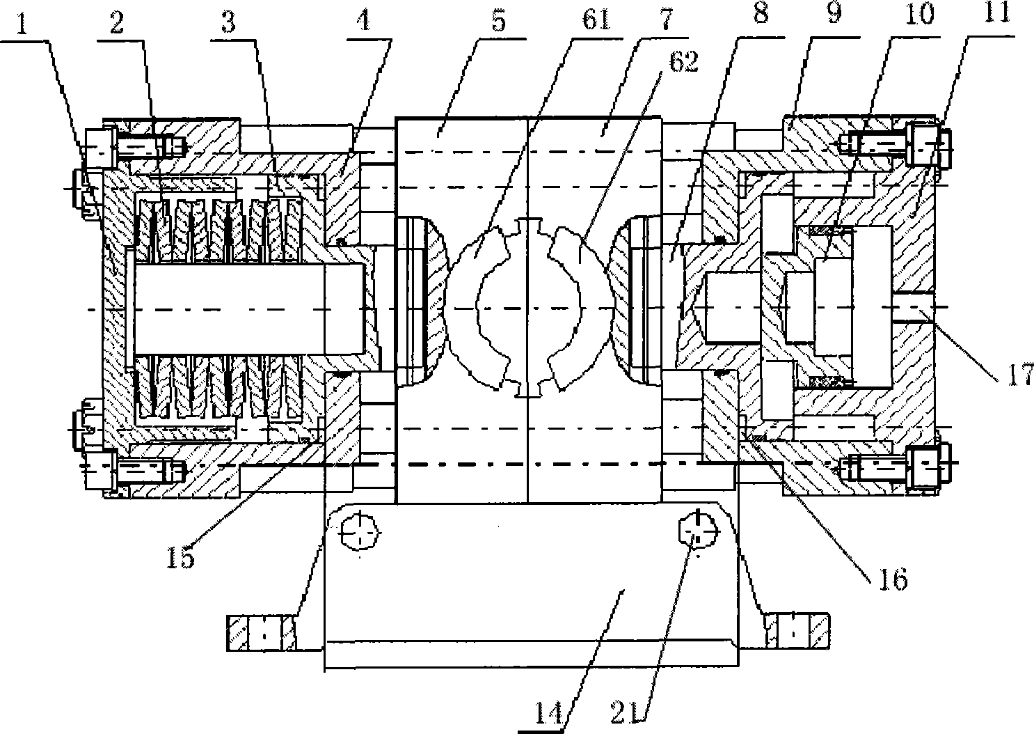
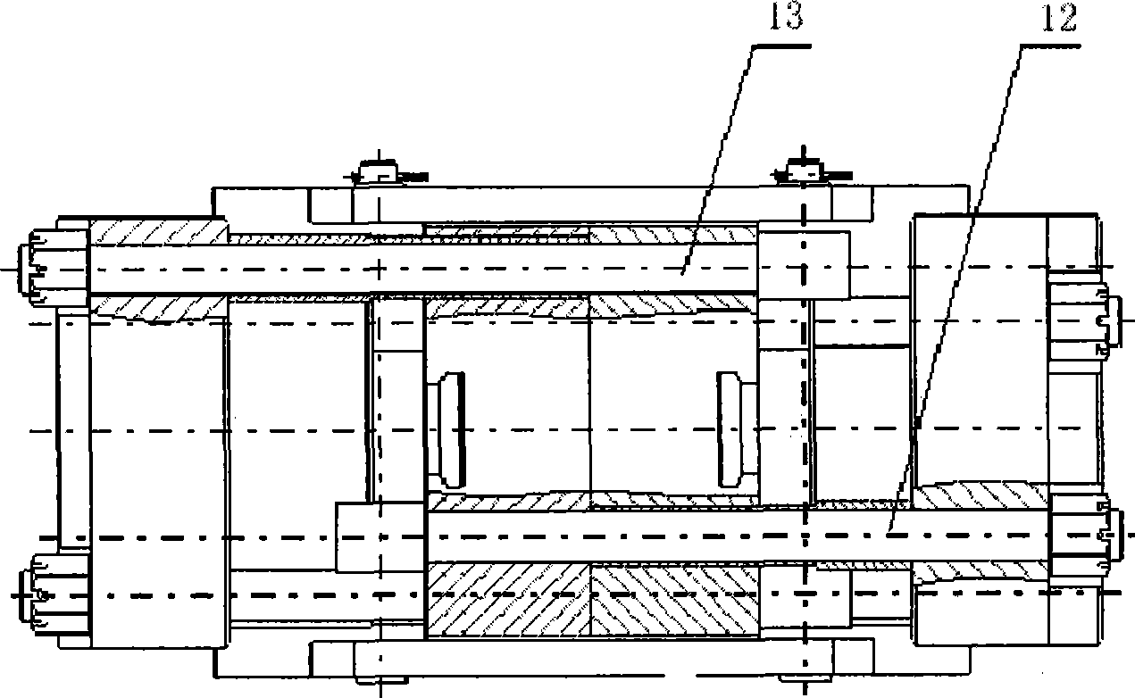
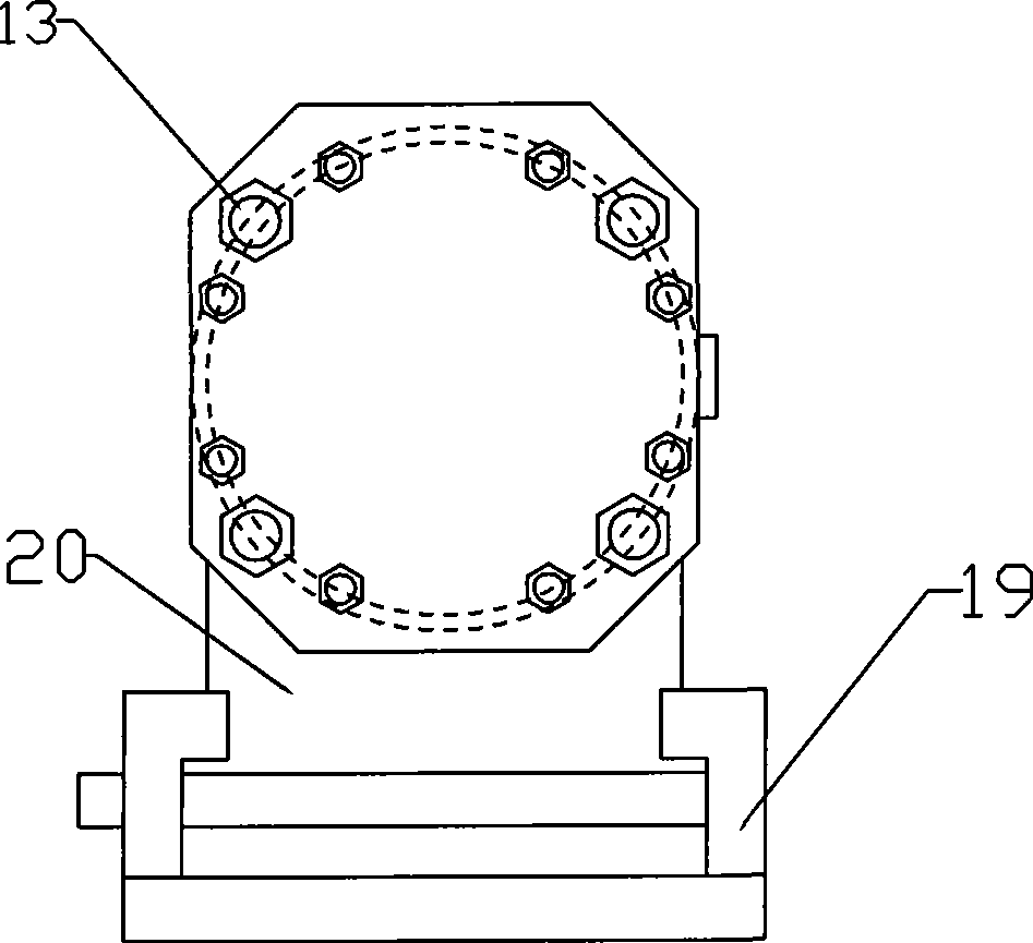
[0026] As shown in the figure, the mining full hydraulic drilling rig linkage hydraulic clamper of the present invention includes a clamper body, the clamper body includes a left clamping device and a right clamping device, and the left clamping device includes a left end cover 1, a left Loosen the oil cylinder body 4, the left loosen piston 3, the left slip 61 and the left slip seat 5, the left loose piston 3 is set inside the left loose oil cylinder body 4, and the left slip 61 is set on the left slip seat 5 And the left slip seat 5 is connected to the top of the left unclamping piston 3 through a dovetail groove, and the bottom of the left unclamping cylinder body 4...


PUM


Abstract

The present invention discloses a mining full hydraulic drill linkage hydraulic clamp fastener which comprises a clamp fastener body. The clamp fastener body comprises a left clamping device and right clamping device which are connected by a pull rod structure and a reinforcement oil cylinder which is arranged in the right clamping device. Compared with the traditional clamp fastener, the clamp fastener is provided with two oil cylinders which push a clamping disc spring open at the same time, and the clamp fastener can be released by less pressure, thereby being good for opening the clamp fastener by the rotation back pressure of the drill and facilitating the drill rotation-propulsion and clamp fastener linkage operation. The clamp fastener can not only use a belleville spring to clamp the a drill rod, but also couple a drill power head driving motor reverse oil passage in the reinforcement oil cylinder and utilize the reverse pressure of the drill to realize reinforcement fastening motion, thus ensuring the reliability of the fastening motion of the drill rod; the clamp fastener is also provided with an automatic float centering structure which can follow the drill rod to center the fastening motion automatically and ensure the operation precision.

Description

technical field [0001] The invention relates to a hydraulic clamping device of a full hydraulic drilling rig, in particular to a mining full hydraulic drilling rig linkage hydraulic clamping device. Background technique [0002] At present, the commonly used hydraulic clamps can be divided into normally closed type and normally open type according to the state of the slips when they are not working. [0003] The normally closed clamp is clamped by the spring and released by the oil cylinder. The clamping force depends on the tension generated by the spring. In order to ensure sufficient clamping force, larger specifications or more springs are required. When clamping, it may be necessary to further compress the spring, so it is necessary to configure a large-section oil cylinder or increase the opening pressure to generate a larger thrust, which causes the structural size of the clamp to increase. In a hydraulic system with linkage function, the opening pressure An increase...

Claims


Application Information

Patent Timeline
Patent Type & Authority Applications(China)
IPC IPC(8): E21B19/10
Inventor 辛德忠陈松林王清峰刁文庆万军陈小平
Owner CHINA COAL TECH & ENG GRP CHONGQING RES INST CO LTD
Learn More