
Micro radiator fan device

A micro heat dissipation and fan technology, which is applied to pump devices, electromechanical devices, and components of pumping devices for elastic fluids, etc., can solve the problems of lack of magnetic conductive back iron structure, insufficient torque, low number of turns and poles, etc. , to achieve the effect of improving convection efficiency and increasing magnetic flux density

Inactive Publication Date: 2011-10-12
IND TECH RES INST
View PDF6 Cites 0 Cited by
  • Summary
  • Abstract
  • Description
  • Claims
  • Application Information

AI Technical Summary

Problems solved by technology

[0004] Others use microplanar coils, but the number of turns and poles is relatively low, the manufacturing cost of the coil is relatively high, and it lacks a proper magnetic back iron structure. When used with high-speed centrifugal blades, the torque is slightly insufficient.

Method used

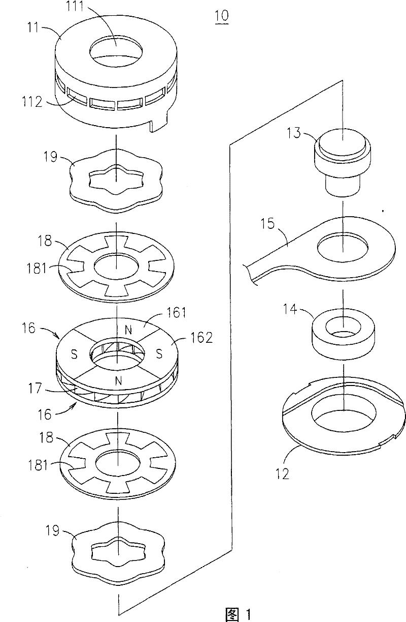
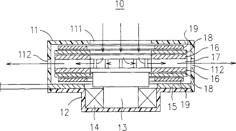
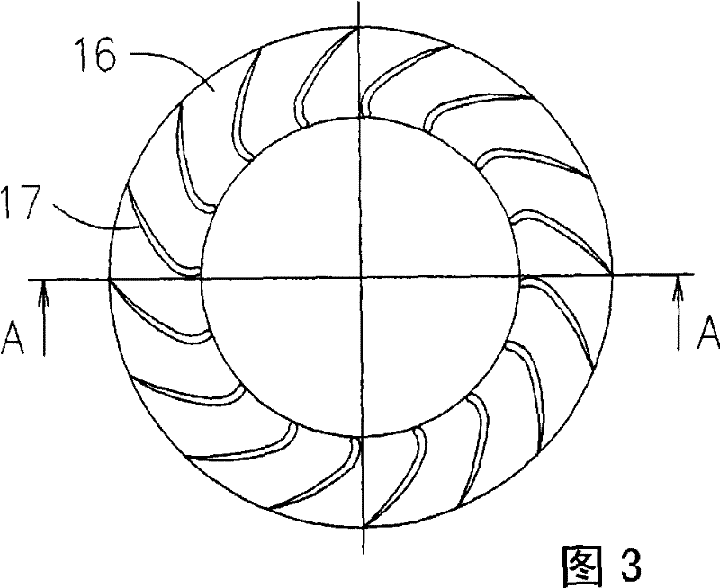

Image

  • Micro radiator fan device
  • Micro radiator fan device
  • Micro radiator fan device

Examples


Embodiment Construction

[0040] In order to have a further understanding and recognition of the structural purpose and effects of the present invention, detailed descriptions are given below in conjunction with the drawings.

[0041] The technical means and effects used by the present invention to achieve the purpose will be described below with reference to the accompanying drawings, and the embodiments listed in the following drawings are only for assistance in understanding the technical solutions of the present invention, but the technical means of the present invention are not Not limited to the drawings listed.

[0042] See figure 1 and figure 2 As shown, the micro-cooling fan device 10 provided by the present invention includes a main body composed of a cylindrical outer sleeve 11 and a flat circular base 12. A rotating shaft 13 is provided in the main body. An axial end is pivotally connected to the base 12 by a bearing 14. The bearing 14 can be a micro ball bearing or a magnetic bearing.

[0043] ...


PUM


Abstract

The invention relates to a micro radiating fan device, mainly consisting of a main body, a rotating shaft, at least one planar coil, at least one permanent magnetic magnet, a plurality of blades and at least one magnetic conductive back iron, wherein, the rotating shaft is pivotally arranged on the main body; the planar coil is arranged in the main body and adopts the way of wave winding; the permanent magnetic magnet is connected with the rotating shaft, is roughly parallel to the planar coil and can produce a staggered and multi-polar magnetic field; a plurality of blades are arranged on the centrifugal blades of the permanent magnetic magnet around the core of the rotating shaft, form an integral body with the permanent magnetic magnet and can synchronously rotate with the permanent magnetic magnet; the magnetic conductive back iron is arranged on one side of the planar coil and has a geometric shape corresponding to the wave forms of the planar coil; in addition, the planar coil is provided with at least one permeable part inside which a hall inductor is arranged; by adopting the structure, the micro radiating fan device achieves the purposes of being thinner, improving convection efficiency and increasing flux density, etc.

Description

Technical field [0001] The present invention relates to a micro-radiation fan device, in particular to a micro-radiation fan device in which centrifugal blades and permanent magnets are integrally formed, and a plane coil is matched with a magnetic back iron designed with a special geometric shape. Background technique [0002] In response to the trend of thinner electronic products, portable products such as notebook computers, 3G mobile phones and PDA phones are widely used. The higher the demand for the central processing unit (CPU), the higher the requirements for heat dissipation. Generally, heat dissipation modules It is mainly composed of a heat dissipation fan with a heat pipe and heat dissipation fins. The heat generated by the electronic components is transferred to the heat dissipation fins through the heat pipe and then radiated to the atmosphere. The heat dissipation fan can provide a convection effect and improve heat transfer efficiency. [0003] The traditional cool...

Claims


Application Information

Patent Timeline
Patent Type & Authority Patents(China)
IPC IPC(8): F04D25/08F04D29/30F04D29/42H02K7/14H02K1/27H02K1/12H02K3/28H02K3/26H02K29/08H01F1/10H01F1/057
Inventor 彭文阳吴东权罗展兴
Owner IND TECH RES INST
Learn More