

LED lamp body and LED lamp comprising same
A technology for LED lamps and lamp bodies, which is applied to lighting and heating equipment, parts of lighting devices, cooling/heating devices of lighting devices, etc. Improve the heat dissipation effect, increase the heat dissipation area, and the effect of large heat dissipation surface
- Summary
- Abstract
- Description
- Claims
- Application Information
AI Technical Summary
Problems solved by technology
Method used
Image

Examples
Embodiment 1
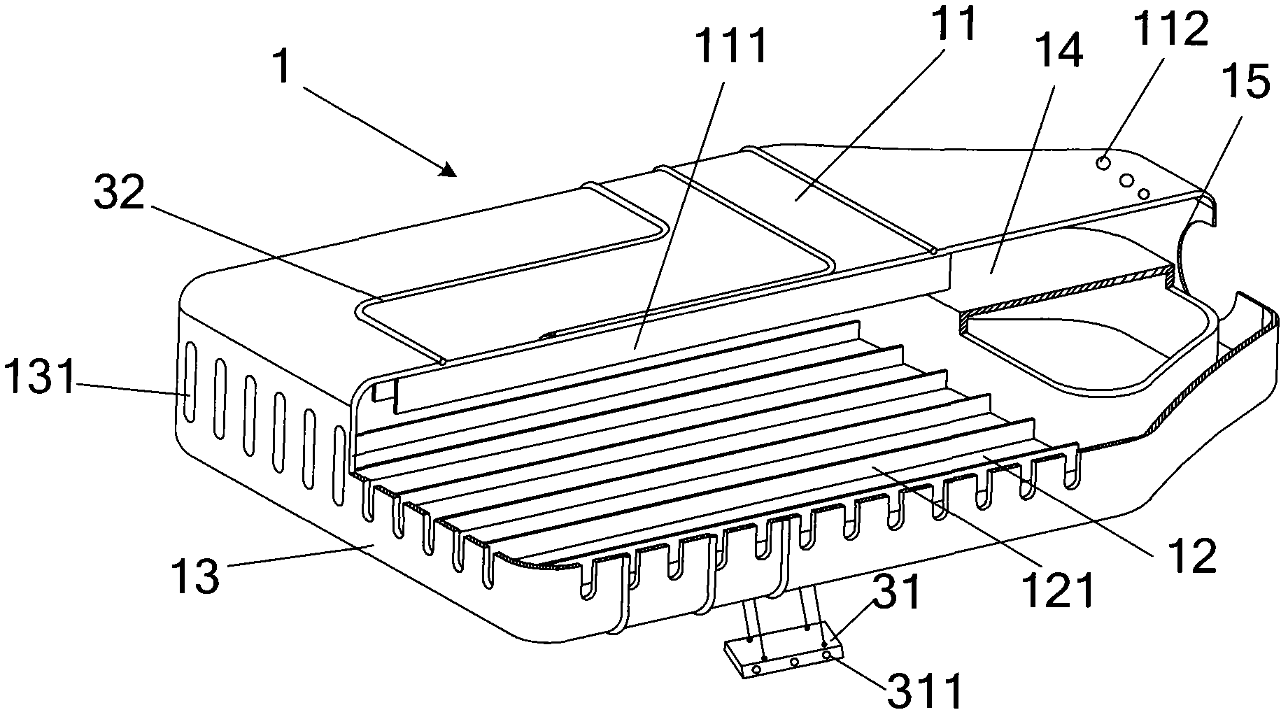
[0038] like figure 1 and 2 As shown, the lamp body 1 of the LED lamp of the present invention includes a box structure composed of a top board 11 , a bottom board 12 and side boards 13 . The lamp body 1 also includes a heat pipe radiator wound around the outer surface of the box structure.
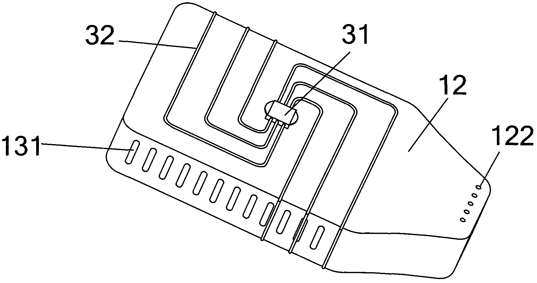
[0039] The heat pipe radiator includes an evaporator 31 and three pipes 32 connected to the evaporator 31 . The evaporator 31 is located on the outer surface of the bottom plate 12, and the pipe 32 is wound around the outer surface of the box structure. One end of the pipeline 32 starts from the evaporator 31 and returns to the other end of the evaporator 31 after passing through the bottom plate, the side plate, the top plate and the other side plate in sequence.
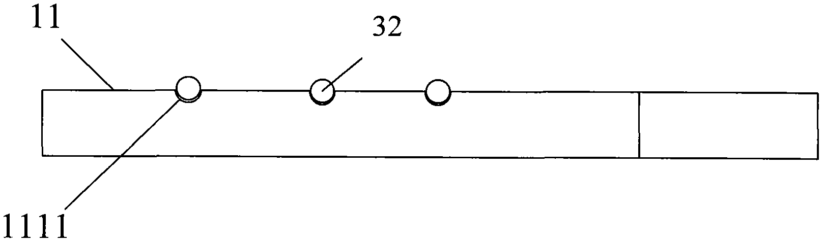
[0040] The pipeline 32 can be fixed on the box structure by welding, and can be arranged on the box structure by integral molding. In addition, those skilled in the art can also set the card slot 1111 at the position where ...
Embodiment 2
[0048] Another example figure 1 and 2 As shown, the lamp body 1 of this embodiment is different from Embodiment 1 in that: the lamp housing in this embodiment is also provided with six heat dissipation fins 111 and heat dissipation fins 111 on the inner surface opposite to the bottom plate 12 Fin121. The heat dissipation fins 111 and the heat dissipation fins 121 can be integrally formed with the top plate 11 and the bottom plate 12 respectively. And the box structure can also be integrally formed.
[0049] In addition, five convection holes 112 and five convection holes 122 are respectively provided on the top plate 11 and the bottom plate 12 . A plurality of convection slots 131 are disposed on the side plate 13 . In particular, the convection grooves 131 arranged on the side plates 13 perpendicular to the extending direction of the heat dissipation fins 111 correspond to the parallel passages formed by the heat dissipation fins 111 and the two parallel side plates, The...
Embodiment 3
[0051] like Figure 5 As shown, this embodiment is a schematic structural diagram of an LED lamp adopting the lamp body in Embodiment 2 of the present invention.
[0052] The circuit board 2 with LED light-emitting elements is fixed on the lower surface of the evaporator 31 by screws 4 . The LED lamp can also include a transparent protective cover 5 . The protective cover 5 and the surface of the lamp body provided with the LED circuit board 2 form a cavity for protecting the LED light-emitting device and the circuit board. Most of the pipes of the heat pipe radiator on the lamp body are located outside the chamber, which can be in direct contact with the external environment for sufficient and effective heat dissipation. In this way, the defect that the heat generated by the LED light-emitting element is all gathered inside the chamber and requires secondary heat exchange in the prior art is overcome, and the heat dissipation efficiency is improved.
[0053] It should be n...
PUM
 Abstract
Description
Claims
Application Information