Shock absorber

A technology of buffers and components, applied in the direction of shock absorbers, shock absorbers, springs/shock absorbers, etc., can solve problems such as difficulty, reduce the degree of freedom of damping force characteristic setting, and achieve the effect of improving the degree of freedom of setting

Inactive Publication Date: 2009-02-11
HITACHI LTD
View PDF1 Cites 6 Cited by
  • Summary
  • Abstract
  • Description
  • Claims
  • Application Information

AI Technical Summary

Problems solved by technology

In this way, since the damping force characteristics in the low, medium and high speed regions of the piston speed interfere with each other, the degree of freedom in setting the damping force characteristics is reduced, and it is difficult to set the most suitable damping force characteristics.

Method used


Image

  • Shock absorber
  • Shock absorber
  • Shock absorber

Examples


Embodiment Construction

[0047] Hereinafter, embodiments of the present invention will be described in detail with reference to the drawings.

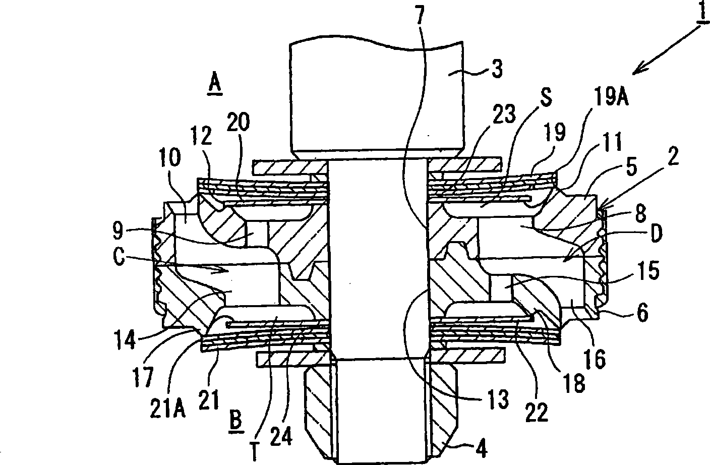
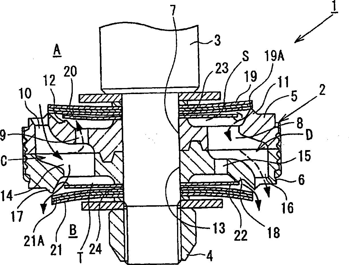
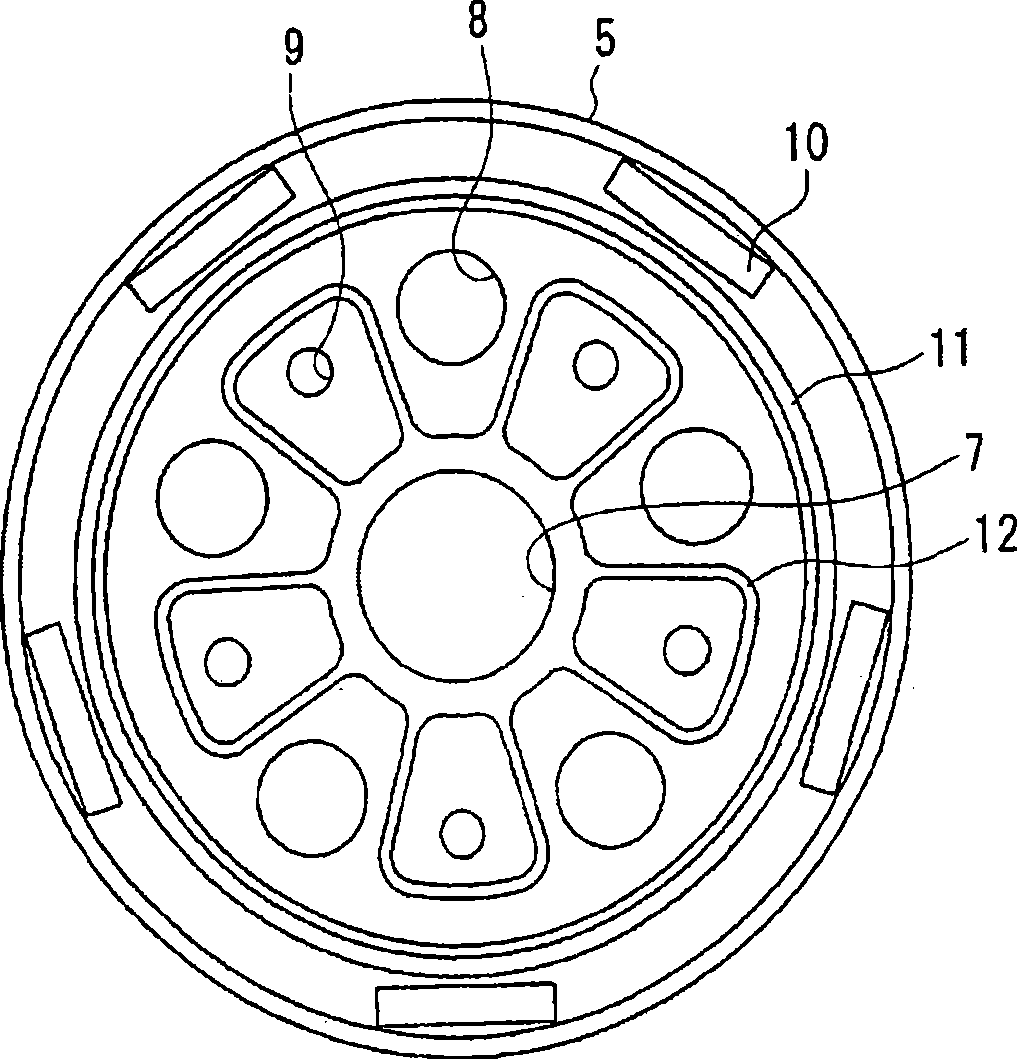
[0048] Regarding the first embodiment of the present invention, refer to Figure 1 to Figure 3 , Figure 14 and Figure 17 Be explained.

[0049] Such as Figure 17 As shown, the hydraulic shock absorber 1 of this embodiment is a cylindrical hydraulic shock absorber mounted on the suspension device of an automobile, and a piston 2 (partition wall member) is slidably fitted in a cylinder 1 a sealed with oil. The piston 2 divides the inside of the cylinder into two chambers, the cylinder upper chamber A and the cylinder lower chamber B. One end of the piston rod 3 is inserted into the piston 2 and connected to the piston 2 through the nut 4, and the other end of the piston rod 3 is inserted into the guide rod 1b and the oil seal 1c installed on the upper end of the cylinder and extends outward. . At the bottom of the cylinder 1a, a free piston 1d is slidab...


PUM


Abstract

A shock absorber can improve set freedom of the damping force characteristics. A piston connected with a piston rod is slidably fitted in a cylinder having a hydraulic fluid sealed therein. An extension-side main disk valve generates a damping force in a high piston speed region against the flow of hydraulic fluid in an extension-side passage. A sub-passage bypasses the extension-side main disk valve, and an extension-side sub disk valve generates a damping force in an intermediate piston speed region. A compression-side main disk valve generates a damping force in the high piston speed region against the flow of hydraulic fluid in a compression-side passage. A sub-passage bypasses the compression-side main disk valve, and a compression-side sub disk valve generates a damping force in the intermediate piston speed region. Damping force characteristics in the intermediate and high piston speed regions can be set according to the valve-opening characteristics of these disk valves. Therefore, it is possible to increase the degree of freedom for setting damping force characteristics.

Description

technical field [0001] The present invention relates to a shock absorber such as a hydraulic shock absorber mounted on a suspension device of a vehicle such as an automobile. Background technique [0002] In general, the cylindrical hydraulic shock absorber installed on the suspension device of vehicles such as automobiles has the following structure, that is, a piston connected to the piston rod is slidably embedded in a cylinder sealed with oil, and a piston connected to the piston rod is slidably embedded. A damping force generating mechanism consisting of an orifice and a disc valve is provided. In this way, the flow of the oil fluid accompanying the sliding of the piston rod in the cylinder is controlled by the orifice and the disc valve, thereby generating a damping force. Next, in the low speed range of the piston speed, the damping force of the orifice characteristic is generated by the orifice, and in the high speed range of the piston speed, the disc valve flexes ...

Claims


Application Information

Patent Timeline
Patent Type & Authority Applications(China)
IPC IPC(8): F16F9/34
CPCF16F9/3484F16F9/3405F16F9/3482
Inventor 神山胜村上裕根津隆
Owner HITACHI LTD
Why Eureka
Try Eureka