Rock quartz micro mechanical gyroscope based on shear stress detection and method for making same

A micromechanical gyroscope, shear stress technology, applied in piezoelectric effect/electrostrictive or magnetostrictive motor, gyroscopic effect for speed measurement, gyroscope/steering induction equipment, etc., can solve the effect of gyro zero offset It is very large, limiting the sensitivity of the micromachined gyroscope, and the complex electrode manufacturing process, etc., to achieve the effect of eliminating the influence of unbalance, novel structure, and improving anti-interference.

Active Publication Date: 2009-02-11
NAT UNIV OF DEFENSE TECH
View PDF2 Cites 18 Cited by
  • Summary
  • Abstract
  • Description
  • Claims
  • Application Information

AI Technical Summary

Problems solved by technology

However, the detection electrodes of these structures need to make two separate electrodes on the side wall of the detection beam, which will lead to a complicated electrode manufacturing process, and the unbalanced positive and negative electrodes have a great influence on the zero bias of the gyroscope.
The detection vibration of these structures has pressure film damping, which makes the quality factor very low, which limits the improvement of the sensitivity of the micromachined gyroscope.

Method used


Image

  • Rock quartz micro mechanical gyroscope based on shear stress detection and method for making same
  • Rock quartz micro mechanical gyroscope based on shear stress detection and method for making same
  • Rock quartz micro mechanical gyroscope based on shear stress detection and method for making same

Examples


Embodiment Construction

[0041] The present invention will be described in further detail below in conjunction with the accompanying drawings and specific embodiments.

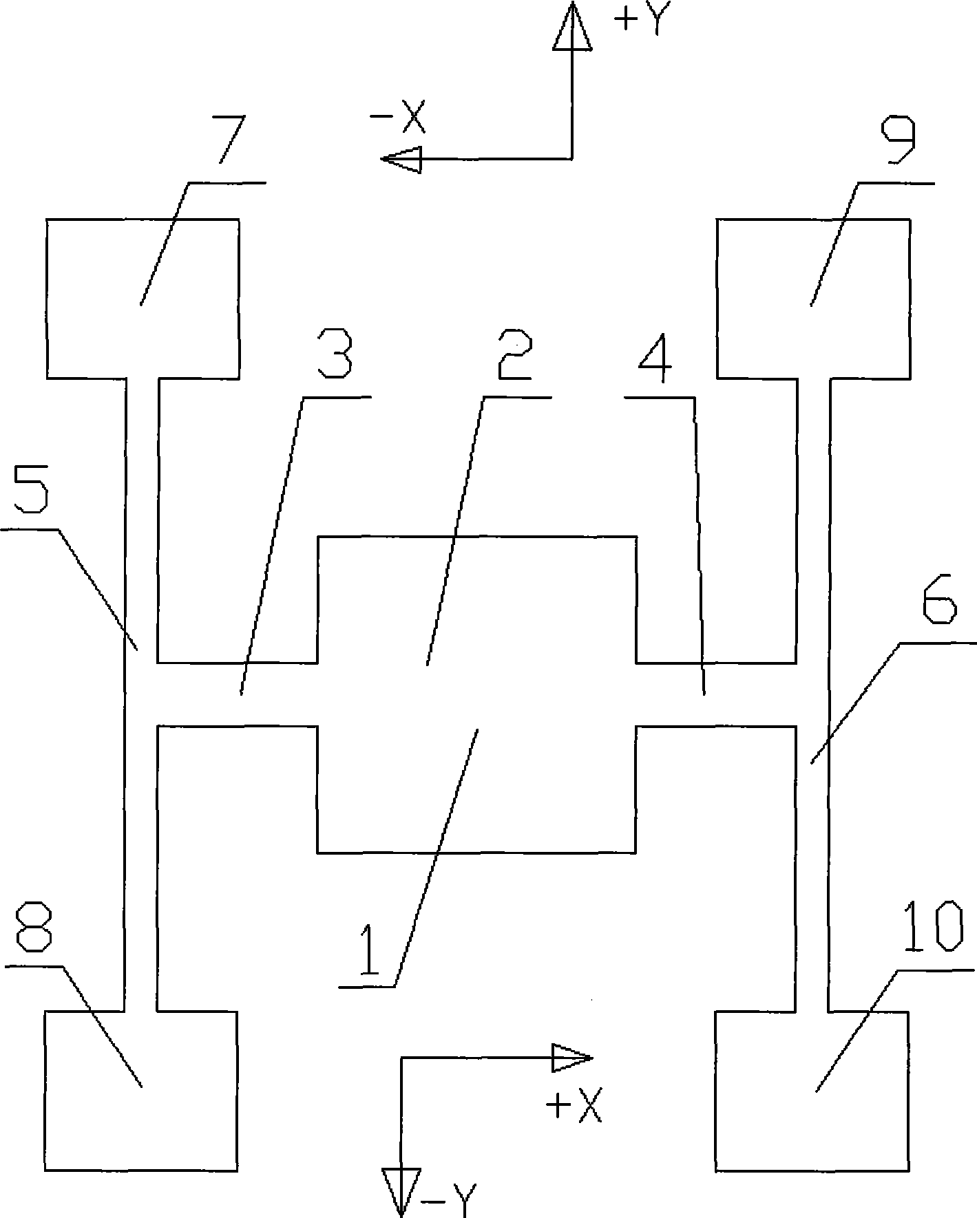
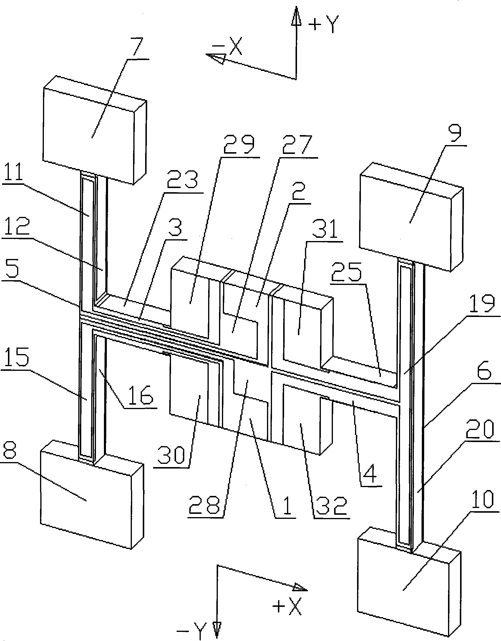
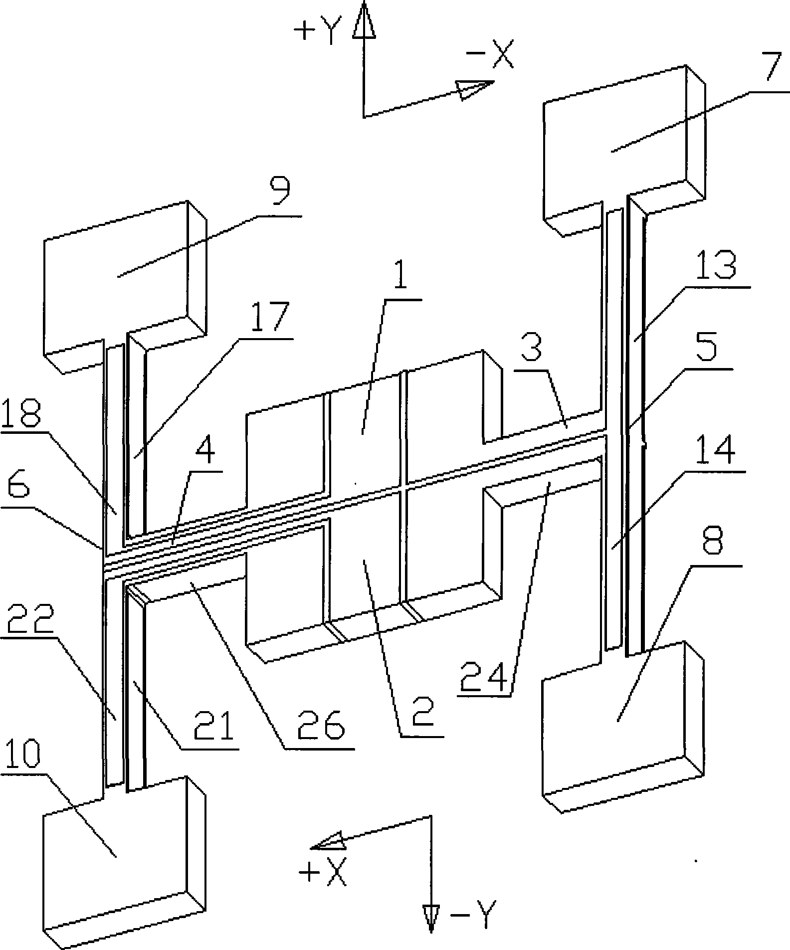
[0042] Such as figure 1 , figure 2 and image 3 Shown, a kind of quartz micromechanical gyroscope based on shear stress detection of the present invention, it comprises support mass block 2, the first cantilever beam 3, the second cantilever beam 4, the first driving beam 5, the second driving beam 6, four A movable mass and a driving electrode and a detecting electrode, the first cantilever beam 3 and the second cantilever beam 4 are symmetrically arranged at both ends of the supporting mass 2, and the supporting mass 2 passes through the first cantilever beam 3 and the first driving beam 5 connected, the supporting mass 2 is connected with the second driving beam 6 through the second cantilever beam 4, and the arrangement direction of the first driving beam 5 and the second driving beam 6 is the same as that of the first cantilev...


PUM


Abstract

The invention relates to a quartz micromechanical gyroscope which is based on the shear stress detection and a manufacturing method. The quartz micromechanical gyroscope comprises a support quality block, a first cantilever beam, a second cantilever beam, a first driving beam, a second driving beam, four movable quality blocks, a driving electrode and a detection electrode; the first cantilever beam and the second cantilever beam are symmetrically arranged on both ends of the support quality block; the support quality block is connected with the first driving beam through the first cantilever beam; the support quality block is connected with the second driving beam through the second cantilever beam; the arrangement direction of the first driving beam and the second driving beam is perpendicular to the arrangement direction of the first cantilever beam and the second cantilever beam; and the four movable quality blocks are respectively fixed at the end parts of the first driving beam and the second driving beam. The invention provides the quartz micromechanical gyroscope which is based on the shear stress detection and has the advantages of simple and compact structure, low cost, simple manufacture process, high sensitivity and strong anti-interference ability and the manufacturing method.

Description

technical field [0001] The invention mainly relates to the field of microelectromechanical systems, in particular to a quartz micromechanical gyroscope based on shear stress detection and a manufacturing method thereof. Background technique [0002] Compared with traditional gyroscopes, quartz micromechanical gyroscopes manufactured using micromechanical technology have the advantages of small size, light weight, low cost, high reliability, and mass production, and can be widely used in aviation, aerospace, weapons, automobiles, etc. , medical, consumer electronics and other fields have huge market potential and have become an important direction for the development of inertial gyroscopes. At present, micro-mechanical gyroscopes of various structures emerge in endlessly in the world, and their common feature is that they have two vibration directions perpendicular to each other, that is, the vibration excitation direction and the detection vibration direction caused by Corio...

Claims


Application Information

Patent Timeline
Patent Type & Authority Applications(China)
IPC IPC(8): G01C19/56B81B7/02B81C1/00G01C19/5656G01C19/5663
Inventor 吴学忠李圣怡谢立强肖定邦董培涛满海鸥王浩旭
Owner NAT UNIV OF DEFENSE TECH
Why Eureka
Try Eureka