Fatigue-tesing machine for ball socket bearing of helicopter main rotor

A fatigue testing machine and main rotor ball technology, applied in the direction of mechanical bearing testing, etc., can solve the problems of too conservative data, waste, and large access to industrial and mining, and achieve the effect of compact structure, convenient operation and maintenance, and beautiful appearance.

Inactive Publication Date: 2009-02-11
YANSHAN UNIV
View PDF0 Cites 30 Cited by
  • Summary
  • Abstract
  • Description
  • Claims
  • Application Information

AI Technical Summary

Problems solved by technology

[0004] The fatigue life test of the spherical hinge bearing of the helicopter main rotor automatic tilter generally adopts the fatigue test method of ordinary bearings, and the reliability of the fatigue life data obtained is low, and some data are too conservative, causing many helicopter main rotor automatic tilter spherical hinge bearing When the rated life is reached, its quality is still very good, and it can still be used, but because the rated life has reached, it has to be replaced, causing a lot of waste
Although the helicopter rotor automatic tilter joint bearing swing-out fatigue testing machine described in document [1] and the helicopter rotor automatic tilter joint bearing swing-in fatigue testing machine described in document [2] have invented two kinds of helicopter main rotor automatic The simulation test device of the spherical hinge bearing of the tilter, but it is quite different from the real industrial and mining of the spherical hinge bearing of the automatic tilter of the main rotor of the helicopter

Method used


Image

  • Fatigue-tesing machine for ball socket bearing of helicopter main rotor
  • Fatigue-tesing machine for ball socket bearing of helicopter main rotor
  • Fatigue-tesing machine for ball socket bearing of helicopter main rotor

Examples


Embodiment Construction

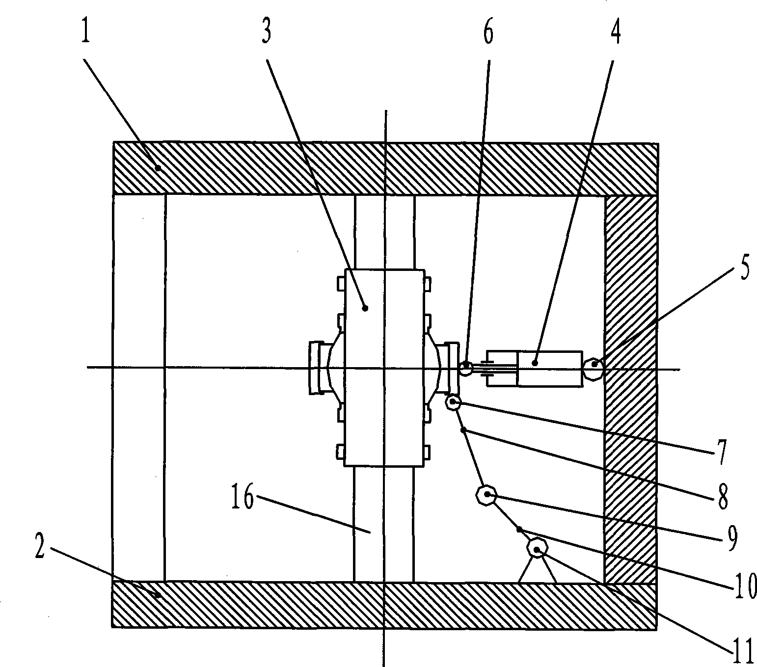
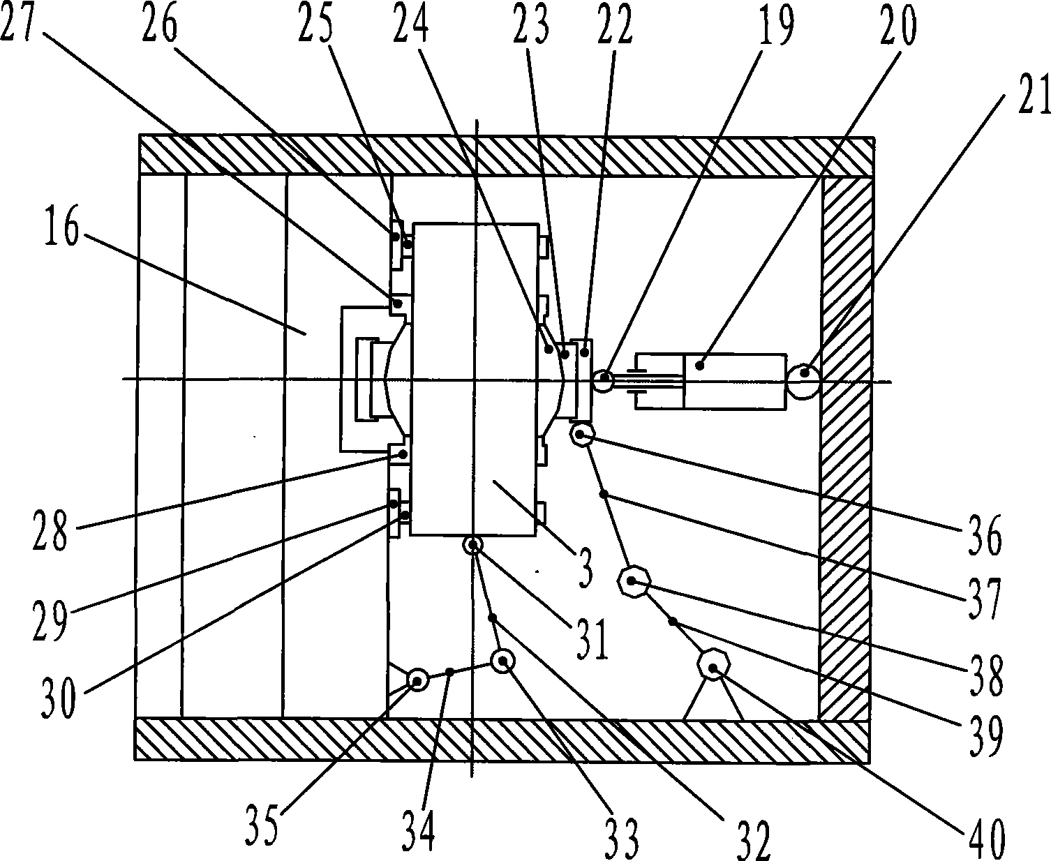
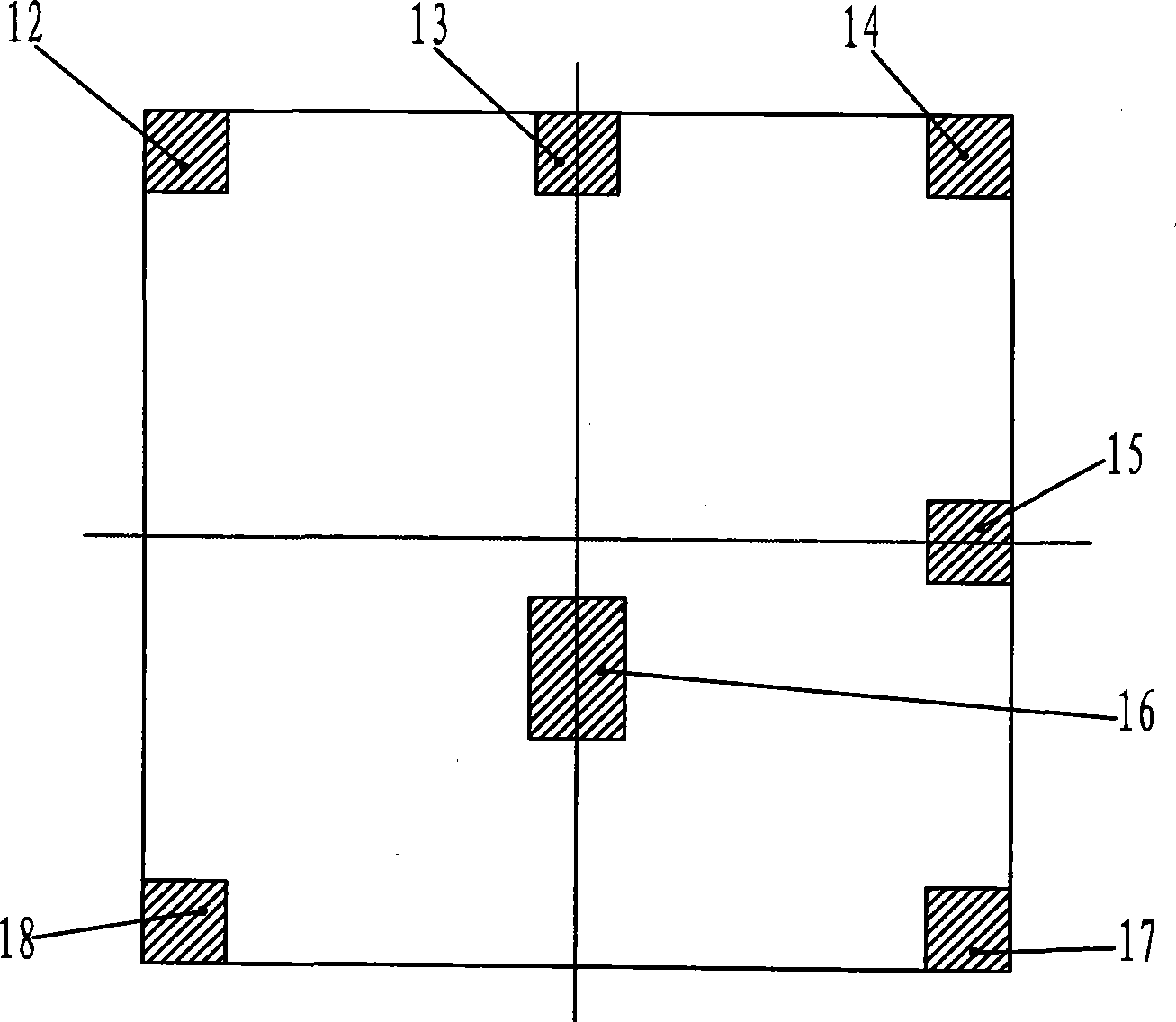
[0014] figure 1 , Figure II , Figure three As an embodiment disclosed by the present invention, the upper platform 1, the lower platform 2, the first side column 12, the second side column 13, the third side column 14, the fourth side column 15, the fifth side column 17, the sixth side column The column 18 and the central column 16 are fixedly connected together to form a frame. The first rolling guide rail 26 and the second rolling guide rail 29 are fixedly connected on the central column 16, the first bearing sleeve 25 is fixedly connected on the first rolling guide rail 26, the second bearing sleeve 30 is fixedly connected on the second rolling guide rail 29, and the second bearing sleeve 30 is fixedly connected on the second rolling guide rail 29. A support sleeve 25 and a second support sleeve 30 jointly support the rotor main shaft 3, the inner hole of the main rotor automatic tilter spherical hinge bearing inner ring 24 matches the outer cylindrical surface of the r...


PUM


Abstract

The invention discloses a fatigue testing machine of a ball socket bearing of a main rotor of a helicopter. The fatigue testing machine is characterized in that a first rolling guide (26) and a second rolling guide (29) are fixedly connected to a central upright post (16); a first supporting sleeve(25) is fixedly connected on the first rolling guide (26); a second supporting sleeve (30) is fixedly connected to the second rolling guide (29); both the first supporting sleeve (25) and the second supporting sleeve (30) support a main shaft of a rotor wing (3); an inner hole of an inner ring (24) of the ball socket bearing of an auto bank unit of a main rotor is matched with an outer cylindrical surface of the main shaft of the rotor wing(3); the inner ring (24) of the ball socket bearing of the auto bank unit of the main rotor is sheathed with an outer ring thereof to form a spherical pair. The invention can accurately simulate the real working conditions of the ball socket bearing of the auto bank unit of the main rotor, such as the temperature, the load, and the like, and accurately simulate the real movements of the ball socket bearing of the auto bank unit of the main rotor, such as the speed, the acceleration and the like. The invention has the advantages of compact structure, beautiful appearance and convenient operation and maintenance.

Description

technical field [0001] The invention relates to a fatigue testing machine for a helicopter main rotor spherical hinge bearing. Background technique [0002] Helicopters are more and more widely used in various fields such as disaster relief, forest protection, and fighting against the enemy because of their advantages such as vertical take-off and landing, no need for take-off and landing runways, maneuverability, and great flexibility. [0003] The helicopter main rotor automatic tilter is the main component of the helicopter control system. By adjusting the attitude of the helicopter main rotor automatic tilter in the air, the helicopter rotor can be tilted forward, backward, left, and right, resulting in forward, Backward, leftward, and rightward horizontal component forces make the helicopter fly forward, backward, left, and right. The performance of the helicopter main rotor automatic tilter has a decisive impact on the flight safety, maneuverability, reliability, flex...

Claims


Application Information

Patent Timeline
Patent Type & Authority Applications(China)
IPC IPC(8): G01M13/04
Inventor 杨育林刘喜平
Owner YANSHAN UNIV
Why Eureka
Try Eureka