Method and apparatus for controlling electric motor

A motor, rotating position technology, applied in the direction of controlling electromechanical transmission devices, controlling generators, emergency protection circuit devices for limiting overcurrent/overvoltage, etc., can solve problems such as reducing and reducing the working range of motors

Active Publication Date: 2009-02-11
TOYOTA IND CORP
View PDF1 Cites 13 Cited by
  • Summary
  • Abstract
  • Description
  • Claims
  • Application Information

AI Technical Summary

Problems solved by technology

This reduces the value of current supplied to the motor and therefore reduces the operating range of the motor

Method used


Image

  • Method and apparatus for controlling electric motor
  • Method and apparatus for controlling electric motor
  • Method and apparatus for controlling electric motor

Examples


Embodiment Construction

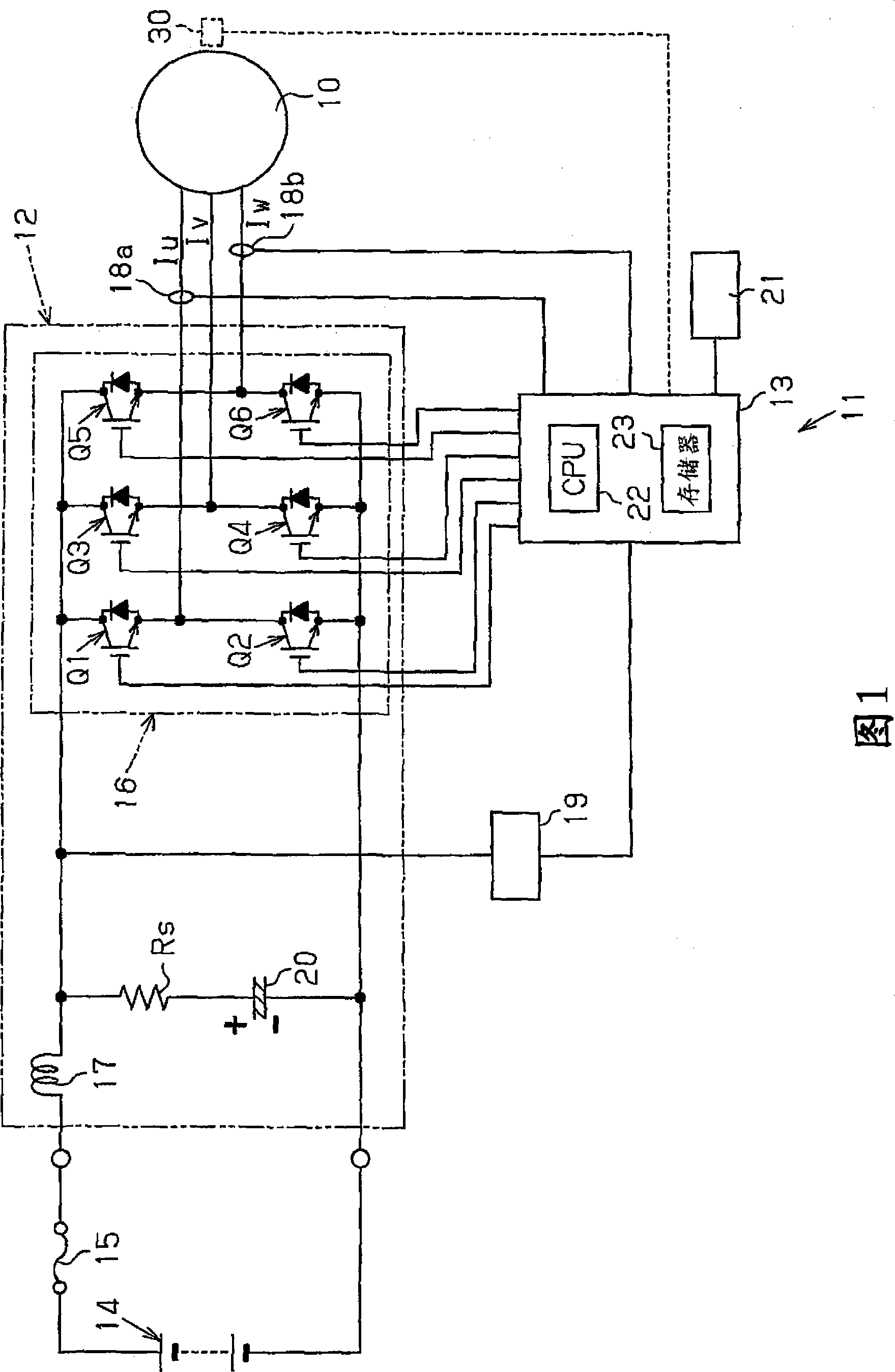
[0022] Reference will now be made to Figure 1 to Figure 5 The control device 11 according to the first embodiment of the present invention will be described. The control device 11 controls a motor 10 for an electric compressor of an air conditioner installed in a vehicle.

[0023] As shown in FIG. 1 , a control device 11 of a motor 10 has an inverter device 12 and a control section 13 serving as a control section of the inverter device. The motor 10 is a three-phase AC motor. The inverter device 12 is connected to the main battery 14 or to a power source for driving the vehicle through a fuse 15 .

[0024] The inverter device 12 includes an inverter circuit 16 having six switching elements Q1, Q2, Q3, Q4, Q5, Q6. Each of switching elements Q1 to Q6 is an IGBT (Insulated Gate Bipolar Transistor). In the inverter circuit 16, the first switching element Q1, the third switching element Q3, and the fifth switching element Q5 are connected in series with the second switching el...


PUM


Abstract

A method and device for controlling the electric motor. The method for controlling a motor current supplied to an electric motor by using an inverter device is provided. The inverter device includes an inverter circuit and a capacitor connected to an input of the inverter circuit. The method includes controlling the inverter circuit in such a manner as to supply an alternating electric current to the electric motor after the temperature of the capacitor reaches a temperature at which a maximum acceptable motor current value becomes greater than or equal to a value at which the torque necessary for starting the electric motor is produced.

Description

technical field [0001] The invention relates to a method and a device for controlling an electric motor using an inverter device. Background technique [0002] PWM-controlled inverter devices for controlling electric motors are generally known. The inverter device uses a power transistor or an IGBT (insulated gate bipolar transistor, insulated gate bipolar transistor) as a control element. The switching speed of power transistors or IGBTs is higher than that of thyristor inverters. Therefore, if the cable (lead wire) connecting the inverter device and the motor is long, a surge voltage greater than twice the inverter output voltage peak value is generated between the terminals of the motor. This surge voltage may damage the coils of the motor or cause insulation breakdown. [0003] Japanese Patent Publication No. 6-38543 discloses a control device for suppressing surge voltage generation. The control device includes a reactor connected to an output terminal of the invert...

Claims


Application Information

Patent Timeline
Patent Type & Authority Applications(China)
IPC IPC(8): H02P6/14H02P6/16H02P27/06H02H9/04H02M7/48H02P21/00H02P21/05H02P21/22H02P23/04H02P23/07H02P27/04H02P27/08
CPCY02T10/643H02M7/48H02P21/14H02P2203/03H02P21/22H02P29/60
Inventor 山田洋平福田仁志
Owner TOYOTA IND CORP
Why Eureka
Try Eureka