Head rest having rotary wing

A technology of rotating wings and headrests, which is applied to special positions of vehicles, underwear, clothing, etc., can solve the problems of complicated installation structure of side headrests, increased production cost of headrests, and easy head injury, so as to avoid passenger injuries and prevent Passenger injury, reduction in production costs

Inactive Publication Date: 2009-02-11
朴茂丸
View PDF0 Cites 2 Cited by
  • Summary
  • Abstract
  • Description
  • Claims
  • Application Information

AI Technical Summary

Problems solved by technology

[0007] Further, when a passenger leans his / her head on the side headrest while a shock is applied to the passenger, the passenger's head hits the side headrest, so his / her head is easily injured
[0008] Furthermore, the conventional side headrest has a complicated installation structure, and thus is heavy and increases the production cost of the headrest

Method used


Image

  • Head rest having rotary wing
  • Head rest having rotary wing
  • Head rest having rotary wing

Examples


Embodiment Construction

[0041] Hereinafter, preferred embodiments of the present invention will be described in detail with reference to the accompanying drawings.

[0042] In the embodiments of the present invention, when describing the same components as those in the related art, the identifiers used when describing the related art are used, and details are not repeated here.

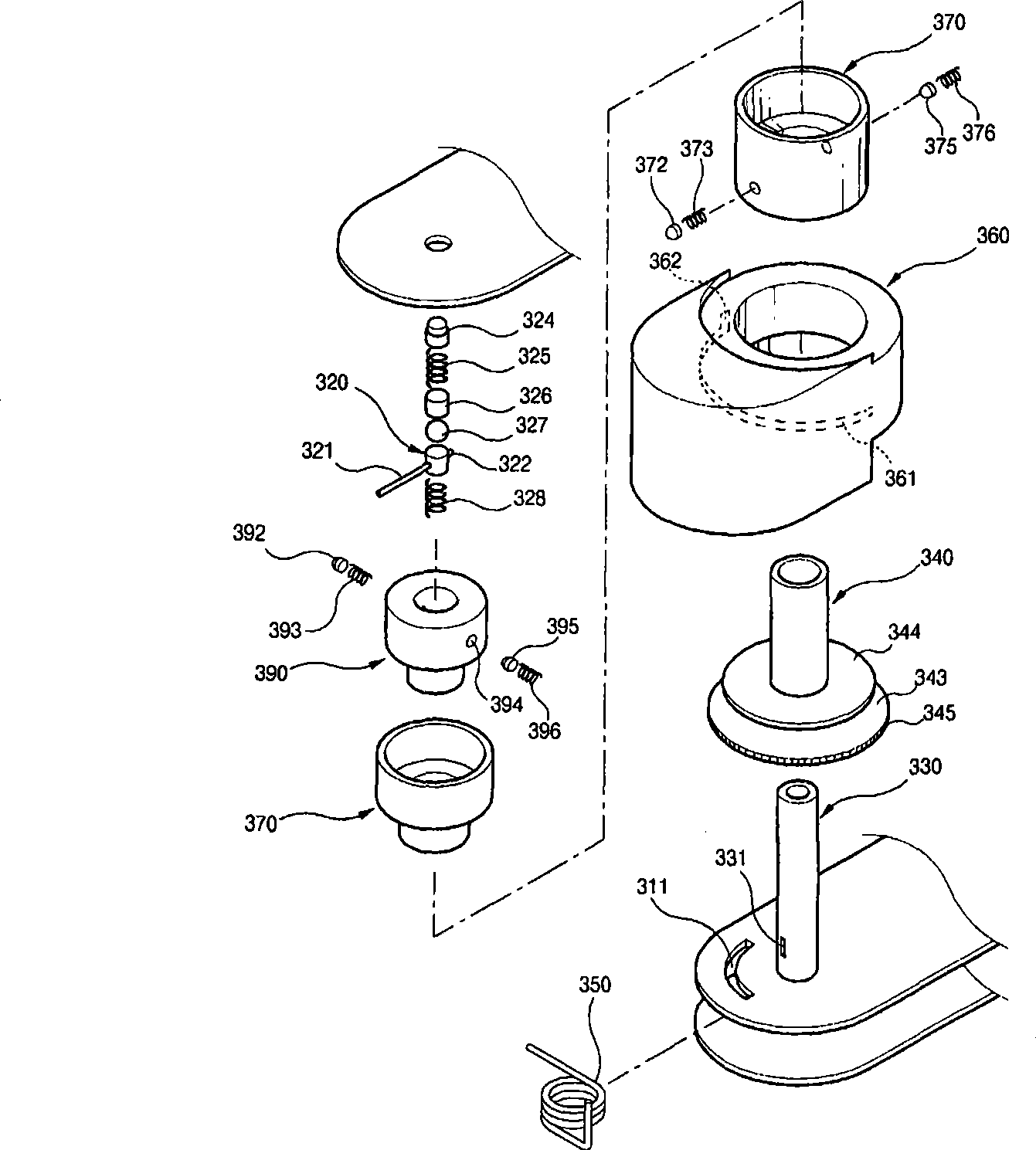
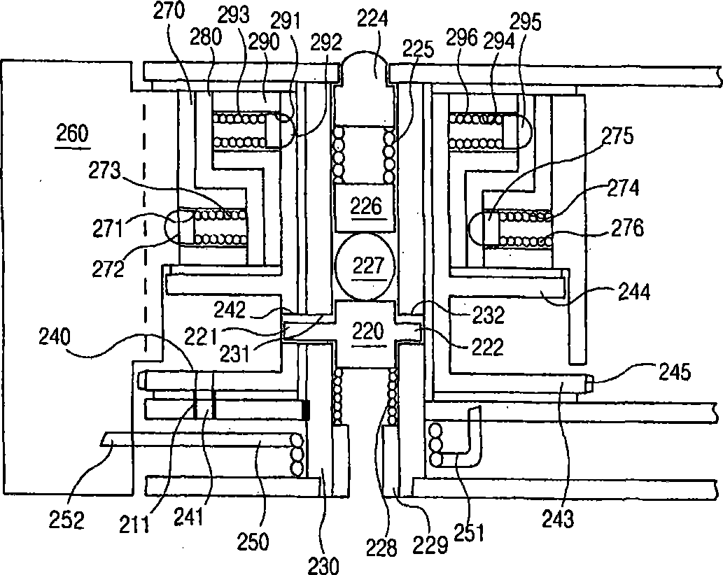
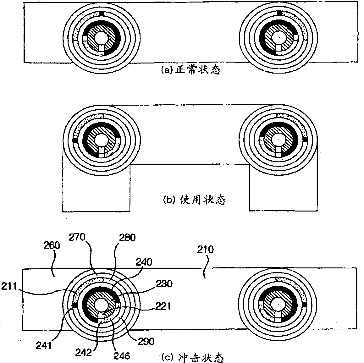
[0043] figure 1 is an exploded perspective view showing a coupling structure of a middle seat portion and a wing unit according to a second embodiment of the present invention. figure 2 Yes figure 1 longitudinal section view. image 3 is a cross-sectional view which schematically shows figure 1 The operation of the coupled structure shown.

[0044] Figure 4is a cross-sectional view schematically showing the operation of the coupling structure of the middle seat portion and the wing unit according to the first embodiment of the present invention. Figure 5 is a longitudinal section view, which shows the Figure 4 The...


PUM


Abstract

The present invention relates to a headrest having a rotary wing. The headrest includes a rotary shaft installed in a seat; a wing unit having a outer casing for receiving the rotary shaft therein; a locking unit for locking the wing unit to the seat; and a return spring for returning the wing unit to an original position of the wing unit. The headrest has a simple construction for rotating the wing unit, which thus reduces the production cost of the headrest.

Description

technical field [0001] The present invention relates generally to head restraints with rotating wings, and in particular to head restraints with rotating wings comprising a wing unit with a housing accommodating an axis of rotation therein, locking the wing unit to a seat The locking unit of the chair body, the return spring for returning the wing unit to the original position of the wing unit, thus have a simple structure for rotating the wing unit and reduce the production cost of the headrest. Background technique [0002] An example of a conventional car seat is found in Korean Utility Model Laid-Open Application No. 1998-37917. [0003] The seat back frame is arranged in the seat back and supports the seat back. The side head restraints are mounted eccentrically on the top surface of the seat back near the main head restraints. At the upper end of the side headrest, a stay having an adjustment knob and extending along the eccentric hole of the side headrest is fixed t...

Claims


Application Information

Patent Timeline
Patent Type & Authority Applications(China)
IPC IPC(8): B60N2/48B60N2/90
CPCA41B9/023A41B2300/20A41B2400/20A41B2400/22A41B2400/36A41B2400/60
Inventor 朴茂丸
Owner 朴茂丸
Why Eureka
Try Eureka