Method and control system for laying a road paving

A technology for regulating systems and covering layers, which is applied in the field of regulating systems and can solve problems such as blockage of leveling cylinders

Active Publication Date: 2009-02-18
JOSEPH VOEGELE AG
View PDF2 Cites 8 Cited by
  • Summary
  • Abstract
  • Description
  • Claims
  • Application Information

AI Technical Summary

Problems solved by technology

The leveling cylinders may become blocked as the tow point controller controls th...

Method used


Image

  • Method and control system for laying a road paving

Examples


Embodiment Construction

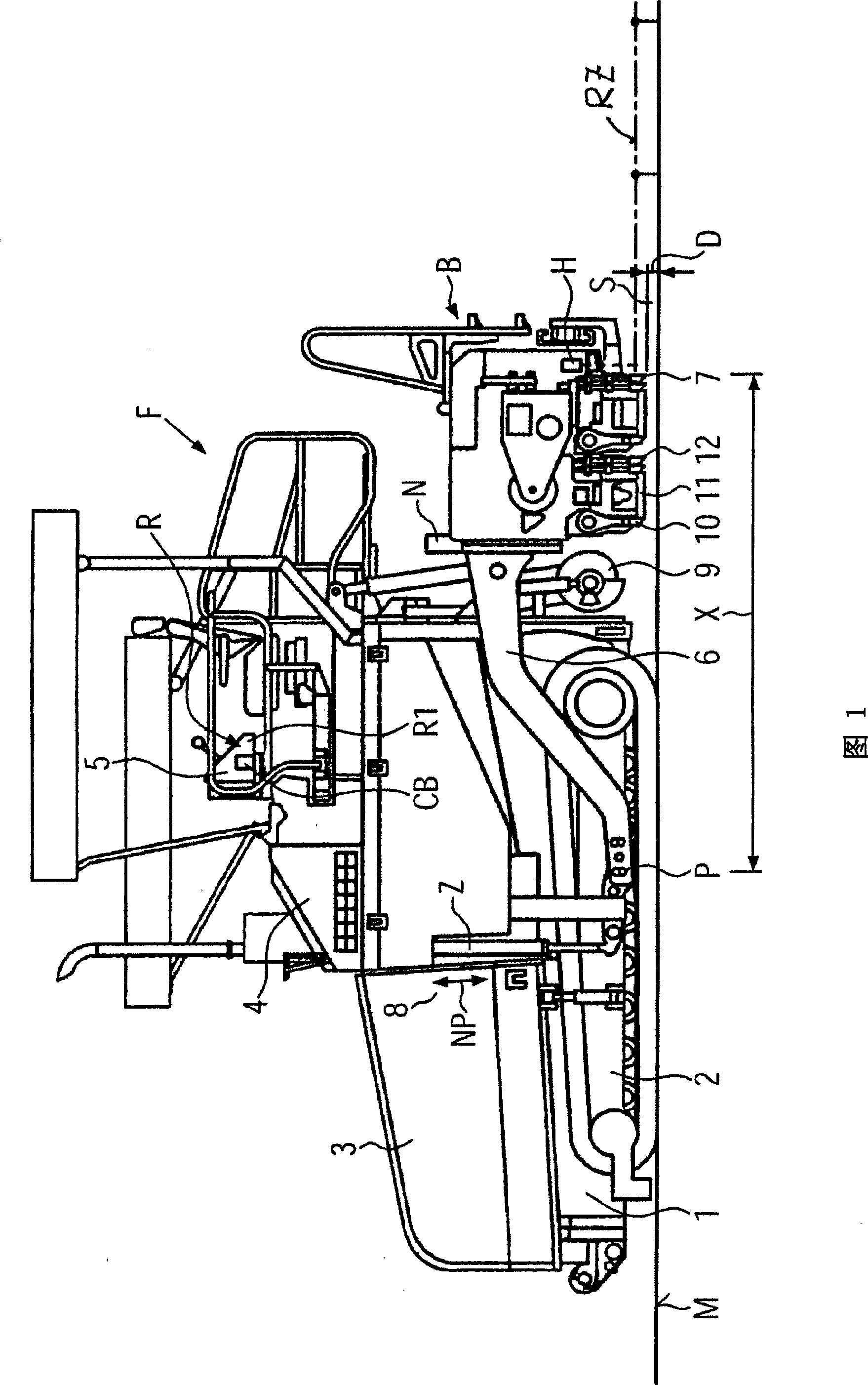
[0015] A road paver F shown in FIG. 1 has a chassis 1 on an undercarriage and a road paving hopper 3 at the front end of the chassis 1 . A main drive source 4 such as a diesel engine is installed in the chassis 1 behind the paving hopper 3 . An operator's platform with a console housing computerized controls 5 is located behind the main drive source 4 . The regulation system R is integrated or connected to the control device 5 . The regulating system R or the control device 5 is equipped with a self-acquiring lay ratio controller R1 which then enlarges or reduces, ie increases or decreases, the value of the earlier input taken into account by the regulating system R. The laying ratio factor, eg when the thickness correction measurement initiated by adjusting the leveling cylinder Z does not yield the desired result at all, or eg after a predetermined duration. In addition, the calculation part CB is provided in the adjustment system R. As shown in FIG. As with conventional ...


PUM


Abstract

According to a method for constructing a cover layer S on a planum M by using a paving screed B the elevation of the paving screed B above the planum M is measured using a reference RZ on the planum M by at least one elevation sensors H and/or the lateral inclination of the paving screed B with respect to the planum M is measured by at least one lateral inclination sensor N. Upon occurrence of a deviation from the target elevation pulling points P of pulling bars 6 of the paving screed B are displaced vertically at a road paver F by levelling cylinders Z. Each levelling cylinder Z is exclusively adjusted over an absolute stroke starting from a selected zero point NP. The absolute stroke is calculated from a measuring result of a reference measurement and by consideration of a construction ratio factor. A new adjustment position of the levelling cylinder Z resulting from the adjustment over the absolute stroke in a self-learning fashion automatically is selected as the new zero point NP for a subsequent regulation cycle.

Description

technical field [0001] The invention relates to a method according to the preamble of claim 1 and to a regulating system according to the preamble of claim 4 . Background technique [0002] In practice, there are various methods for correcting the thickness of the covering layer when laying traffic pavements. [0003] According to existing methods, elevation sensors are mounted at the front of the paving machine, at the rear end of the paving machine near the lateral distribution device, at the paving screed, and sometimes, at the tie bars of the paving fleet. A height sensor is used to measure the thickness by scanning a reference (eg routing wire or by a skid sliding on a flat surface). Then, based on the detected deviation (thickness too thin or too thick), the leveling cylinders are adjusted in each direction for a period of time until the target thickness of the covering layer is reached again. A large number of height sensors leads to high costs and complex signal pr...

Claims


Application Information

Patent Timeline
IPC IPC(8): E01C19/48E01C23/01G01B21/08G05D3/20
CPCE01C19/008E01C19/4873
Inventor 延斯·赫尔曼
Owner JOSEPH VOEGELE AG
Why Eureka
Try Eureka