Fatigue test apparatus of vehicle manual brake controlling mechanism
A fatigue test and operating mechanism technology, which is applied in the testing of machines/structural components, measuring devices, and vehicle testing, etc., and can solve the problems of heavy counterweights, heavy counterweights, and inconvenient operation
- Summary
- Abstract
- Description
- Claims
- Application Information
AI Technical Summary
Problems solved by technology
Method used
Image

Examples
Embodiment Construction
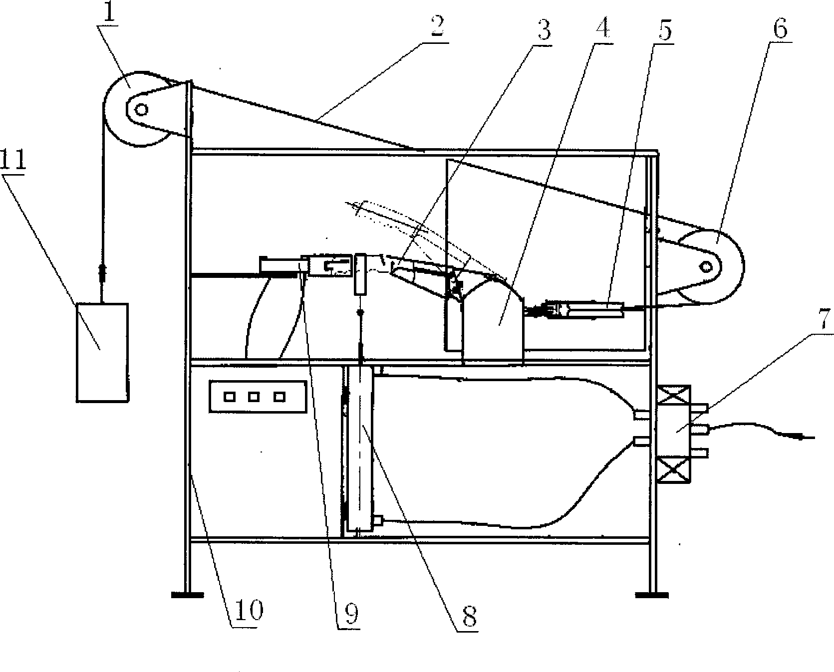
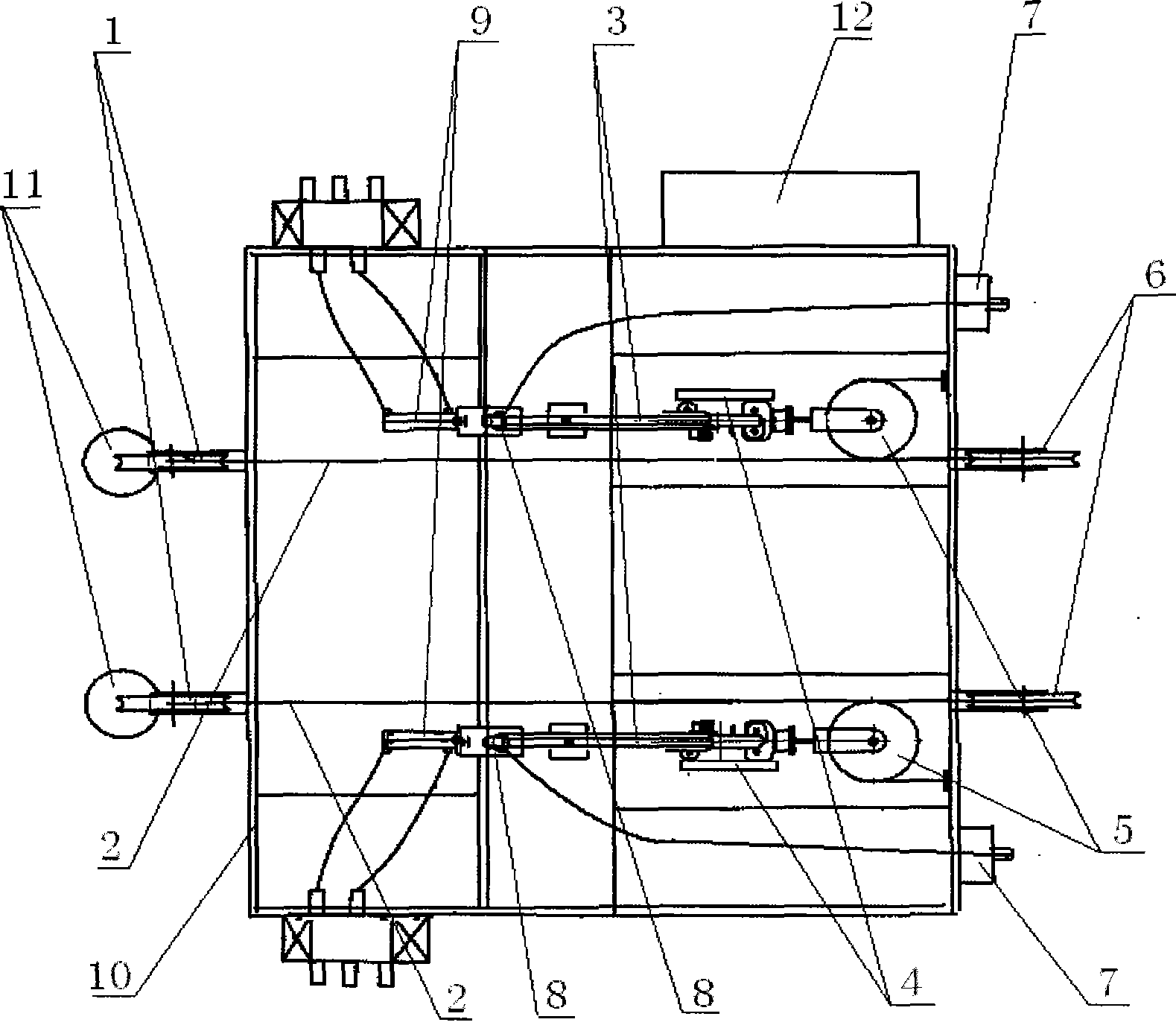
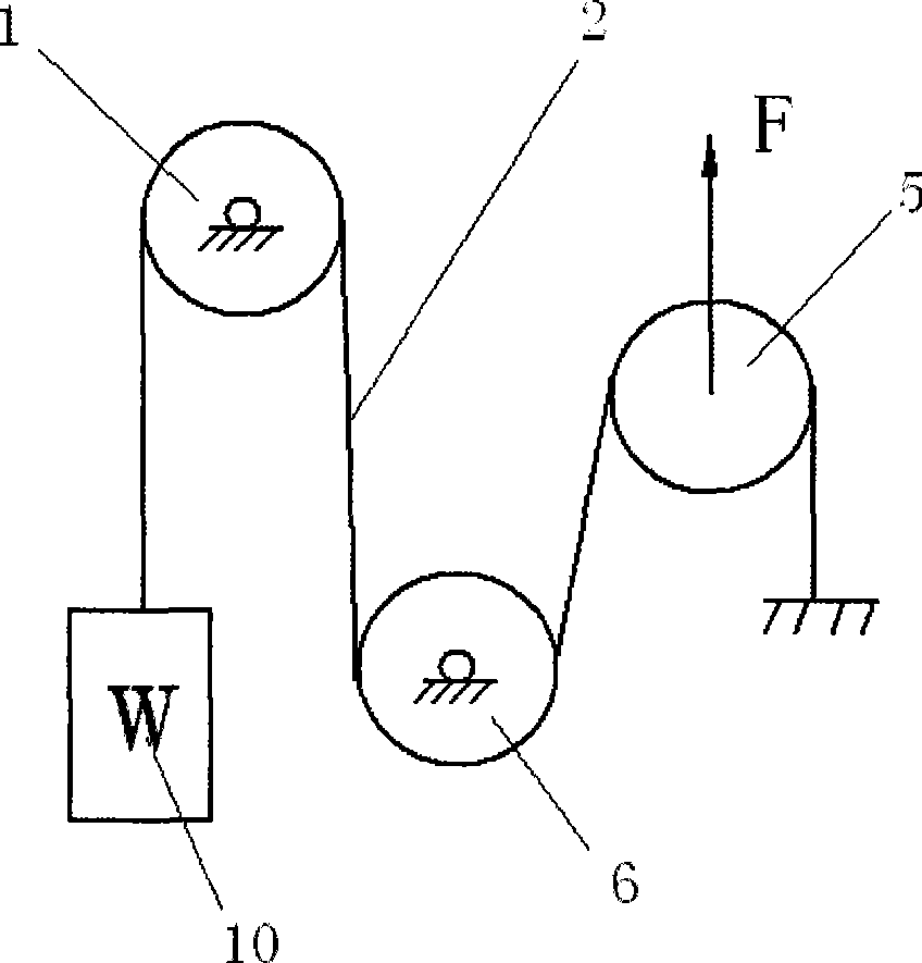
[0015] Such as figure 1 , figure 2 , image 3 , Figure 4 As shown, the automobile hand brake operating mechanism fatigue test device includes a frame 10, two fatigue test mechanical units, a solenoid valve 7, and an electric control box 12, and each fatigue test mechanical unit includes a horizontal The support plate, the specimen mounting bracket 4 on the upper surface of the support plate, the cylinder I8, the cylinder II9, the first fixed pulley 1, the second fixed pulley 6, the movable pulley 5, the steel cable 2 and the counterweight 11, the axis of the cylinder I8 and the cylinder II9 Cross, the first fixed pulley 1 is located at the top of one side of the frame 10, the second fixed pulley 6 is located at the other side of the frame 10, one end of the steel cable 2 is fixed on the frame 10, and the other end of the steel cable 9 is connected with a counterweight block 11, the steel cable 2 passes through the movable pulley 5, the second fixed pulley 6 and the first ...
PUM
 Abstract
Description
Claims
Application Information
 - Generate Ideas
- Intellectual Property
- Life Sciences
- Materials
- Tech Scout
- Unparalleled Data Quality
- Higher Quality Content
- 60% Fewer Hallucinations
Browse by: Latest US Patents, China's latest patents, Technical Efficacy Thesaurus, Application Domain, Technology Topic, Popular Technical Reports.
© 2025 PatSnap. All rights reserved.Legal|Privacy policy|Modern Slavery Act Transparency Statement|Sitemap|About US| Contact US: help@patsnap.com