

Detection apparatus and detection method
A technology of detection device and detection method, which is applied in the direction of measurement device, optical instrument test, machine/structural component test, etc.
- Summary
- Abstract
- Description
- Claims
- Application Information
AI Technical Summary
Problems solved by technology
Method used
Image

Examples
Embodiment Construction
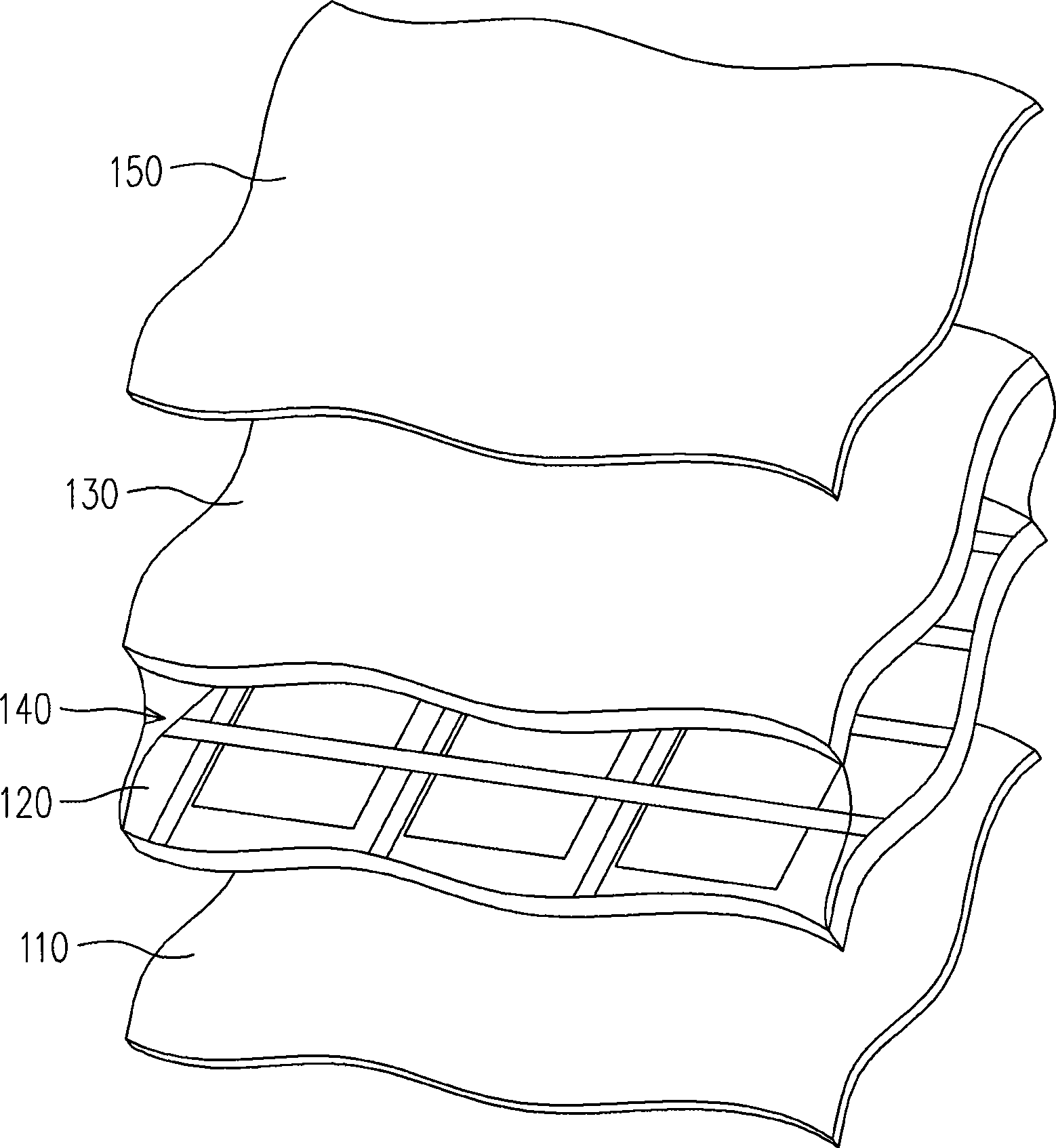
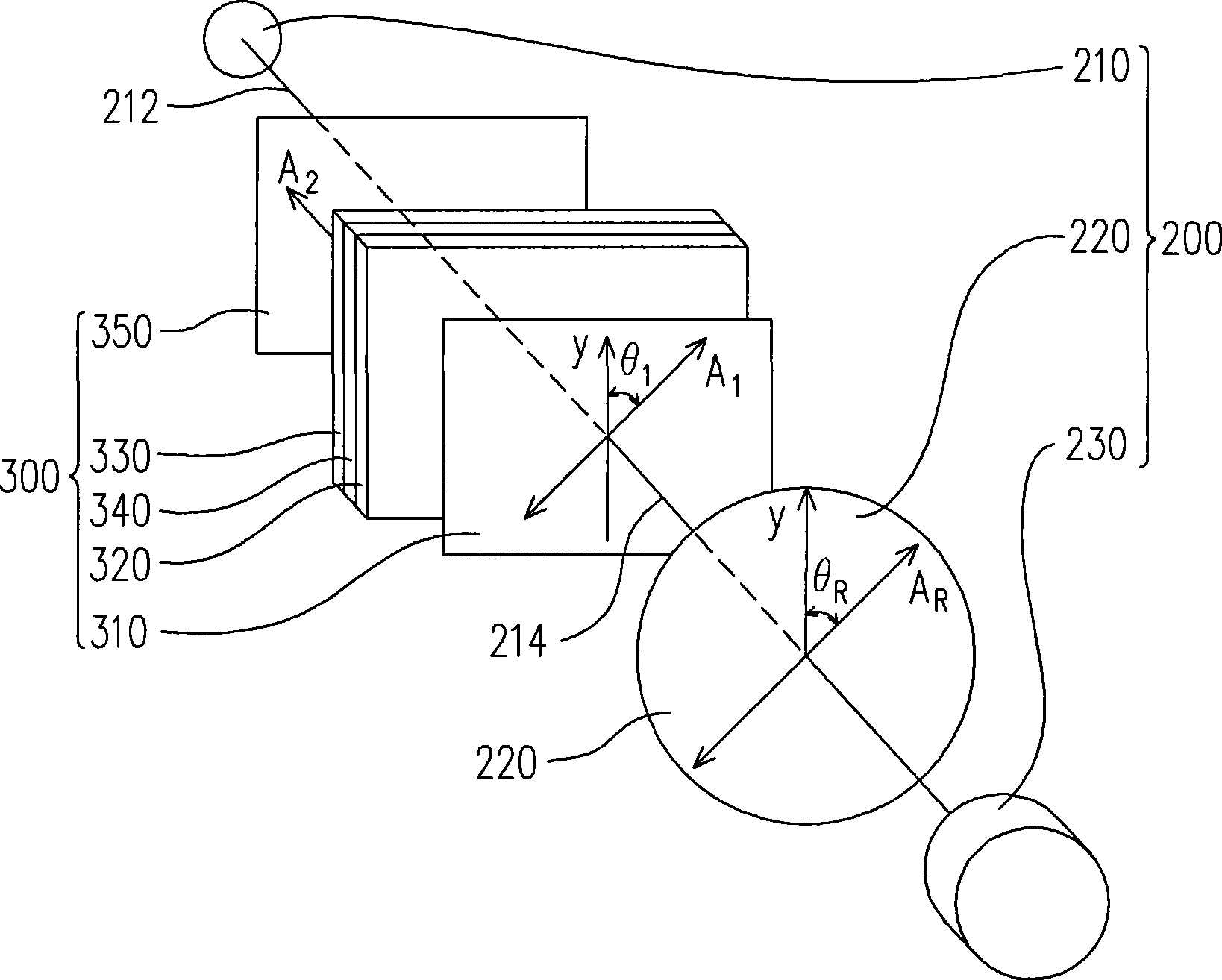
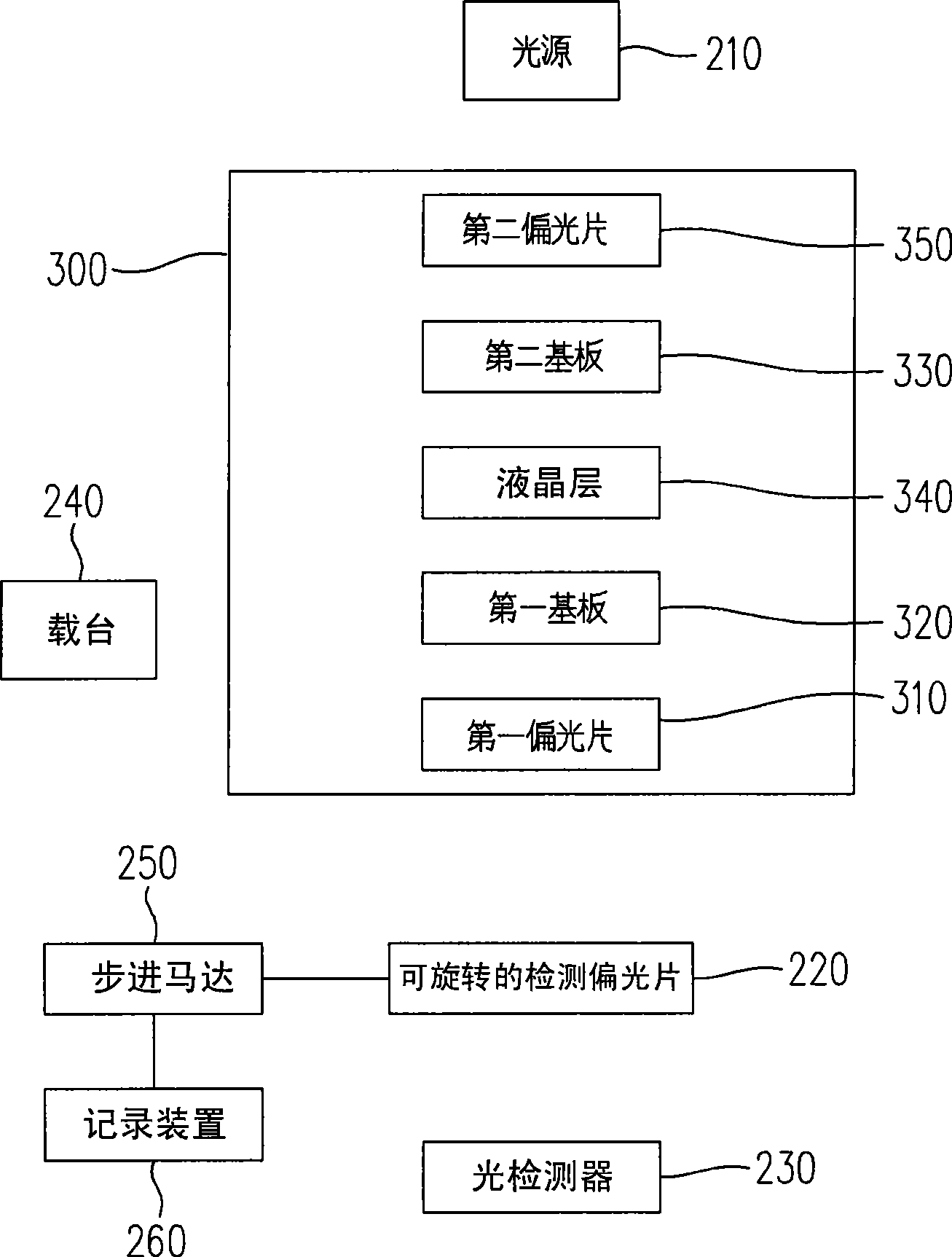
[0053] Figure 2A It is an exploded schematic diagram of a detection device according to an embodiment of the present invention, and Figure 2B It is a block diagram of a detection device according to an embodiment of the present invention. Please refer to Figure 2A and Figure 2B , the detection device 200 is suitable for detecting a light absorption axis A of a first polarizer 310 of a liquid crystal panel 300 1 angle, and the liquid crystal panel 300 also includes a first substrate 320, a second substrate 330, a liquid crystal layer 340 and a second polarizer 350, wherein the liquid crystal layer 340 is disposed between the first substrate 320 and the second substrate 330 , and the first polarizer 310 is disposed on the first substrate 320 , and the first polarizer 310 and the liquid crystal layer 340 are located on two sides of the first substrate 320 respectively. In addition, the second polarizer 350 is disposed on the second substrate 330 and located between the se...
PUM
 Abstract
Description
Claims
Application Information