Manufacturing process of aluminum electrolytic capacitor for reducing point discharge phenomenon

An aluminum electrolytic capacitor, cutting-edge discharge technology, applied in the direction of electrolytic capacitors, capacitors, capacitor terminals, etc., can solve the problems that the product life cannot reach the expected target, short-circuit breakdown, breakdown, etc., to reduce discharge phenomena, prolong product life, The effect of reducing mid-term failure phenomenon

Active Publication Date: 2009-02-18
SHANGHAI YONGMING ELECTRONICS
View PDF0 Cites 3 Cited by
  • Summary
  • Abstract
  • Description
  • Claims
  • Application Information

AI Technical Summary

Problems solved by technology

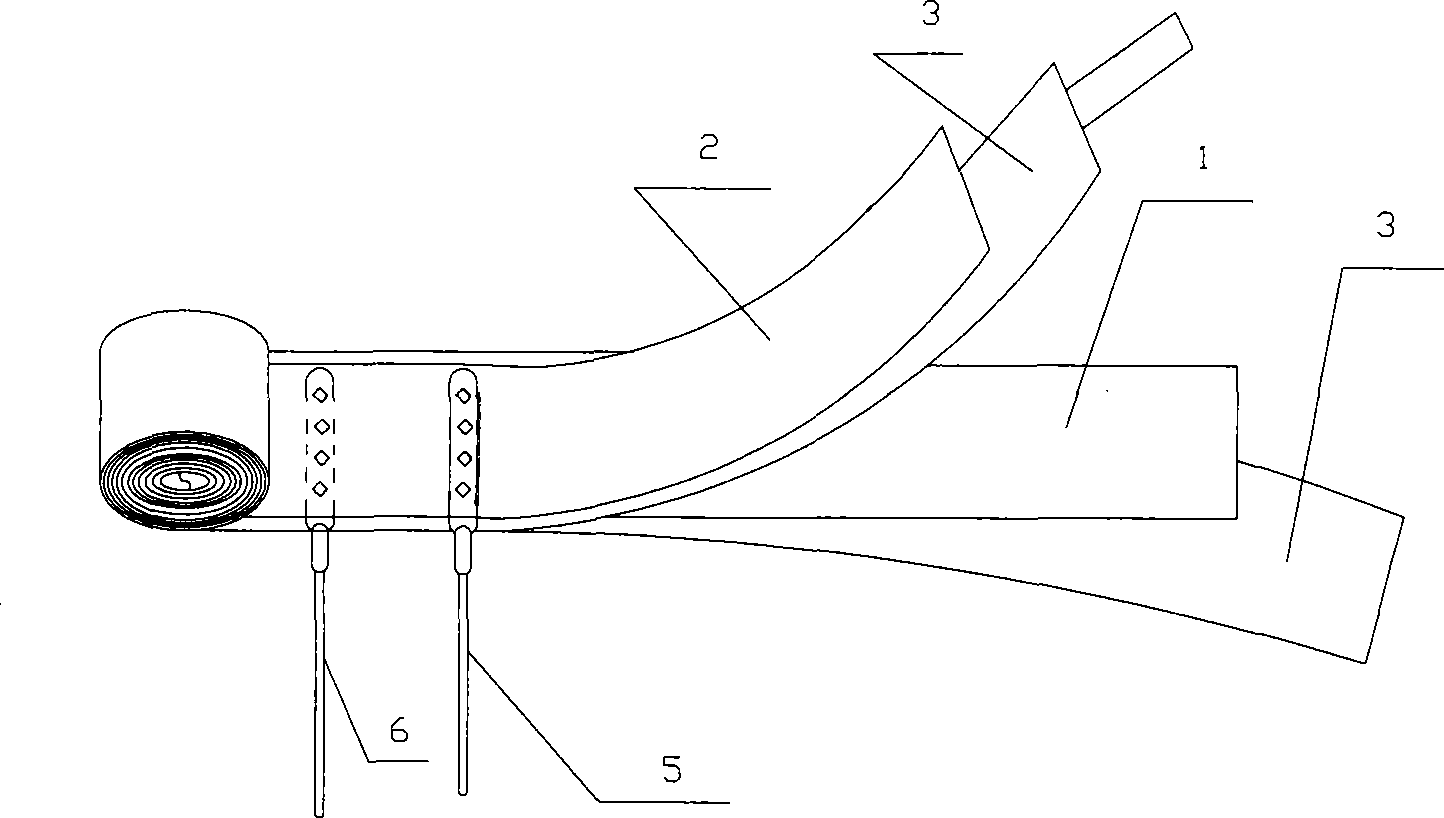
[0002] At present, in the existing aluminum electrolytic capacitor production process, such as figure 1 As shown, the tongue of the positive guide pin 6 is set on the positive electrode aluminum foil 1, the tongue of the negative guide pin 5 is set on the bottom of the negative electrode aluminum foil 2, and the positive electrode aluminum foil 1, the negative electrode aluminum foil 2, and the positive electrode aluminum foil 1 are respectively provided. There is a layer of electrolytic paper 3. There are large burrs on the edge of the aluminum tongue of the positive guide pin 6 and the negative guide pin 5, while the other side has almost no burrs. When the guide pin burrs touch the electrolytic paper, the burrs may pierce the electrolytic paper. Lead to short-circuit breakdown; and the tip discharge effect will occur at the burr of the guide pin in the energized state, and the product will either fail early or have partial breakdown in the middle of use, resulting in a product life that cannot reach the expected goal

Method used


Image

  • Manufacturing process of aluminum electrolytic capacitor for reducing point discharge phenomenon
  • Manufacturing process of aluminum electrolytic capacitor for reducing point discharge phenomenon
  • Manufacturing process of aluminum electrolytic capacitor for reducing point discharge phenomenon

Examples


Embodiment 1

[0016] like figure 1 As shown, it is a schematic diagram of the structure of an aluminum electrolytic capacitor. A manufacturing process of an aluminum electrolytic capacitor that reduces the tip discharge phenomenon is:

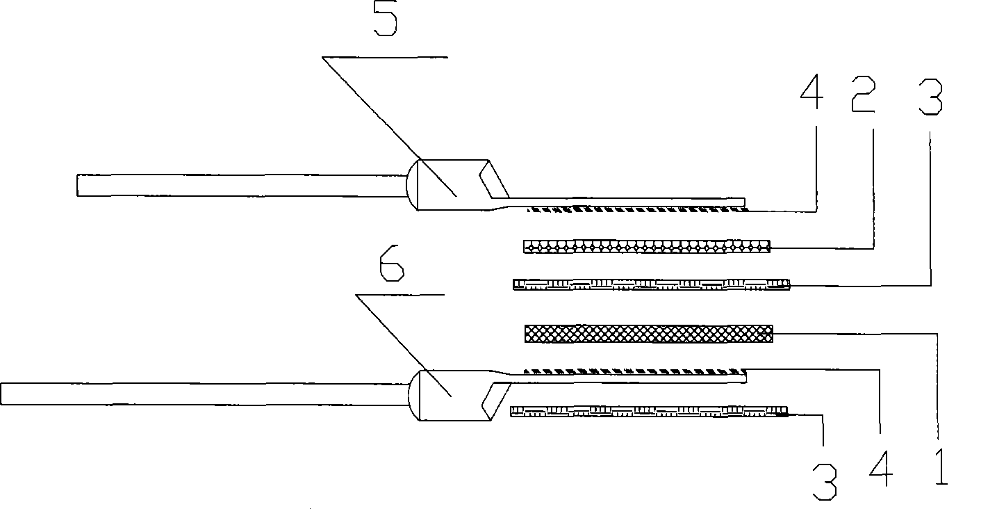
[0017] first step, such as figure 2 As shown, first select the surface of the positive guide pin 6 and the negative guide pin 5, set the tongue of the positive guide pin 6 under the positive electrode aluminum foil 1, and the side with the burr 4 is in contact with the foil surface of the positive electrode aluminum foil 1, and place the negative The tongue of the guide pin 5 is arranged on the negative electrode aluminum foil 2, and the side with the burr 4 is in contact with the foil surface of the negative electrode aluminum foil 2, and a layer of electrolytic paper 3 is respectively arranged between the positive electrode aluminum foil 1 and the negative electrode aluminum foil 2 and under the positive guide pin 6, The burr-free side of the positive gu...

Embodiment 2

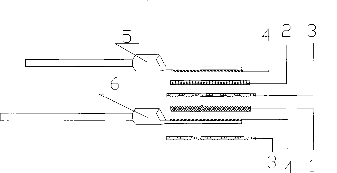
[0020] like image 3 As shown, it is a schematic diagram of the manufacturing process of the present invention in Embodiment 2, and a manufacturing process of an aluminum electrolytic capacitor that reduces tip discharge phenomenon is:

[0021] The first step is to select the surface of the positive guide pin 6 and the negative guide pin 5, set the tongue of the positive guide pin 6 under the positive electrode aluminum foil 1, and the side with burrs is in contact with the foil surface of the positive electrode aluminum foil 1, and place the negative The tongue part of the guide pin 5 is arranged on the top of the negative electrode aluminum foil 2, and the side with burrs is in contact with the foil surface of the negative electrode aluminum foil 2, and a layer of electrolytic paper 3 is respectively arranged between the positive electrode aluminum foil 1 and the negative electrode aluminum foil 2 and under the positive guide pin 6, The burr-free sides of the positive guide ...

Embodiment 3

[0024] like Figure 4 As shown, it is a schematic diagram of the manufacturing process of the present invention in Embodiment 3, and a manufacturing process of an aluminum electrolytic capacitor that reduces tip discharge phenomenon is:

[0025] The first step is to select the surface of the positive guide pin 6 and the negative guide pin 5, set the tongue of the positive guide pin 6 under the positive electrode aluminum foil 1, and the side with burrs is in contact with the foil surface of the positive electrode aluminum foil 1, and place the negative The tongue of the guide pin 5 is arranged on the top of the negative aluminum foil 2, and the side with burrs is in contact with the foil surface of the negative aluminum foil 2, and a layer of electrolytic paper 3 is respectively provided between the positive aluminum foil 1 and the negative aluminum foil 2 and under the positive guide pin 6, The positive guide pin 6 and the negative guide pin 5 face each other, and the burrs 4...


PUM


Abstract

The invention relates to a process for manufacturing an aluminum electrolytic capacitor to reduce point discharge phenomenon, which is characterized in that, firstly a positive guide needle and a negative needle select surfaces, a tongue part of a positive guide needle is provided on the positive electrode aluminum foil, one surface with burr is contacted with a foil surface of the positive electrode aluminum foil, a tongue part of a negative guide needle is provided under the negative electrode aluminum foil, one surface with burr is contacted with a foil surface of the negative electrode aluminum foil, a layer of electrolytic papers are respectively arranged between the positive electrode aluminum foil and the negative electrode aluminum foil and under the positive electrode aluminum foil, a surface without burr of the positive guide needle is contacted with the electrolytic papers, the positive guide needle and the negative guide needle are back to back, burrs of the two guide needles are face to face, the aluminum electrolytic capacitor is prepared according to the common process. The invention has advantages that the guide pin aluminum tongue burr can not transpierce the electrolytic papers and can reduce the burr point discharge phenomenon, thereby extending life of the product and greatly reducing the product middle-period invalidation phenomenon.

Description

technical field [0001] The invention relates to a manufacturing process of an aluminum electrolytic capacitor that reduces tip discharge phenomenon, and belongs to the technical field of the manufacturing process of an aluminum electrolytic capacitor. Background technique [0002] At present, in the existing aluminum electrolytic capacitor production process, such as figure 1 As shown, the tongue of the positive guide pin 6 is set on the positive electrode aluminum foil 1, the tongue of the negative guide pin 5 is set on the bottom of the negative electrode aluminum foil 2, and the positive electrode aluminum foil 1, the negative electrode aluminum foil 2, and the positive electrode aluminum foil 1 are respectively provided. There is a layer of electrolytic paper 3. There are large burrs on the edge of the aluminum tongue of the positive guide pin 6 and the negative guide pin 5, while the other side has almost no burrs. When the guide pin burrs touch the electrolytic paper, ...

Claims


Application Information

Patent Timeline
IPC IPC(8): H01G9/00H01G9/045H01G9/048H01G9/14H01G9/008
Inventor 严丽芳
Owner SHANGHAI YONGMING ELECTRONICS
Why Eureka
Try Eureka