

Generator rotor and production method thereof
A generator rotor and manufacturing method technology, which is applied in the manufacture of motor generators, electromechanical devices, electrical components, etc., can solve problems such as generator burnout, and achieve the effect of strengthening mechanical strength
- Summary
- Abstract
- Description
- Claims
- Application Information
AI Technical Summary
Problems solved by technology
Method used
Image

Examples
Embodiment Construction
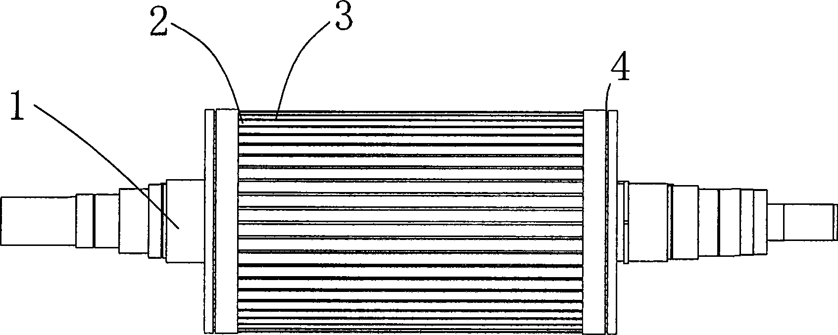
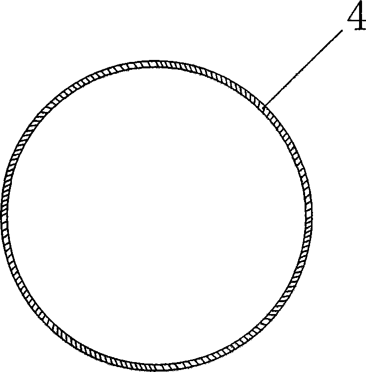
[0014] like figure 1 , figure 2 The engine rotor shown includes a main shaft 1, a rotor core 2 and a coil 3; the rotor core is installed on the main shaft, and there are evenly distributed grooves on its outer peripheral surface; the coil is embedded in the slot of the rotor core, and the coil There are joints at the end and wrapped with insulating film or wool weft tape; the two ends of the rotor core are covered with insulating hoops 4 slightly larger than the outer circle of the coil end, and the coil is between the rotor core and the insulating hoop. At the end, the insulating hoop is a steel hoop and a multi-layer high-temperature insulating film is wrapped on the steel hoop. Of course, it can also be other components; a high-temperature-resistant insulating layer is wrapped outside the insulating hoop, and the high-temperature-resistant insulating layer is high-temperature resistant The insulating film layer or the wool weft tape, obviously, can also be other high temp...
PUM
 Abstract
Description
Claims
Application Information