
RGB to RGBW color decomposition method and system

A technology of color decomposition and RGB values, applied in color signal processing circuits, cathode ray tube indicators, instruments, etc., can solve problems such as picture quality deterioration

Active Publication Date: 2009-02-18
SAMSUNG ELECTRONICS CO LTD
View PDF0 Cites 74 Cited by
  • Summary
  • Abstract
  • Description
  • Claims
  • Application Information

AI Technical Summary

Problems solved by technology

Aspects of the present invention also provide an RGB-to-RGBW color decomposition method and system capable of solving the The problem of image quality deterioration caused by

Method used


Image

  • RGB to RGBW color decomposition method and system
  • RGB to RGBW color decomposition method and system
  • RGB to RGBW color decomposition method and system

Examples


Embodiment Construction

[0025] Reference will now be made in detail to the present embodiments of the invention, examples of which are illustrated in the accompanying drawings, wherein like reference numerals refer to like parts throughout. The embodiments are described below in order to explain the present invention by referring to the figures.

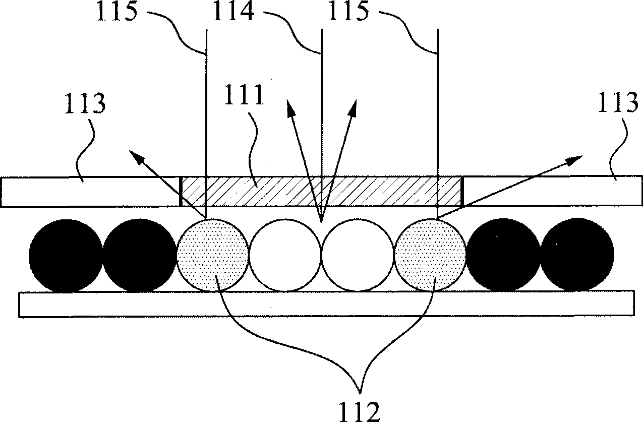
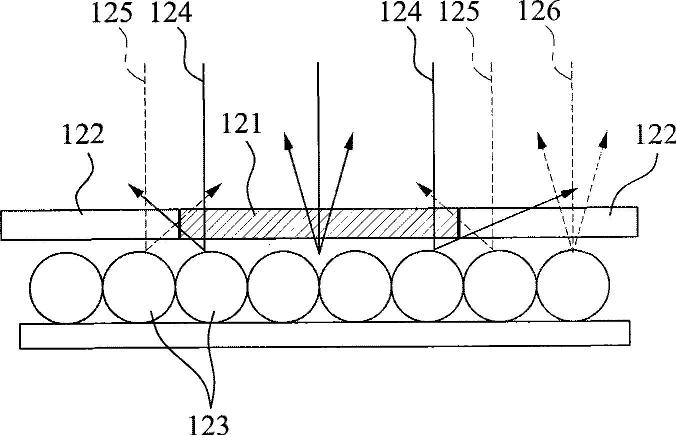
[0026] Figure 1A and Figure 1B Driving of a reflective type display in which a partition wall between sub-pixels does not exist in the related art is shown. Reflective type displays exhibit greater crosstalk between channels than existing liquid crystal displays (LCDs). Two causes of crosstalk will be described below.

[0027] First, crosstalk can occur because when a signal is sent to each subpixel, the amount of signal in the surrounding subpixels affects how well the subpixel's reflector is converted to white or black. Such as Figure 1A As shown, when only the red sub-pixel 111 is bright (on), as the reflector approaches the outer end, all the refl...


PUM


Abstract

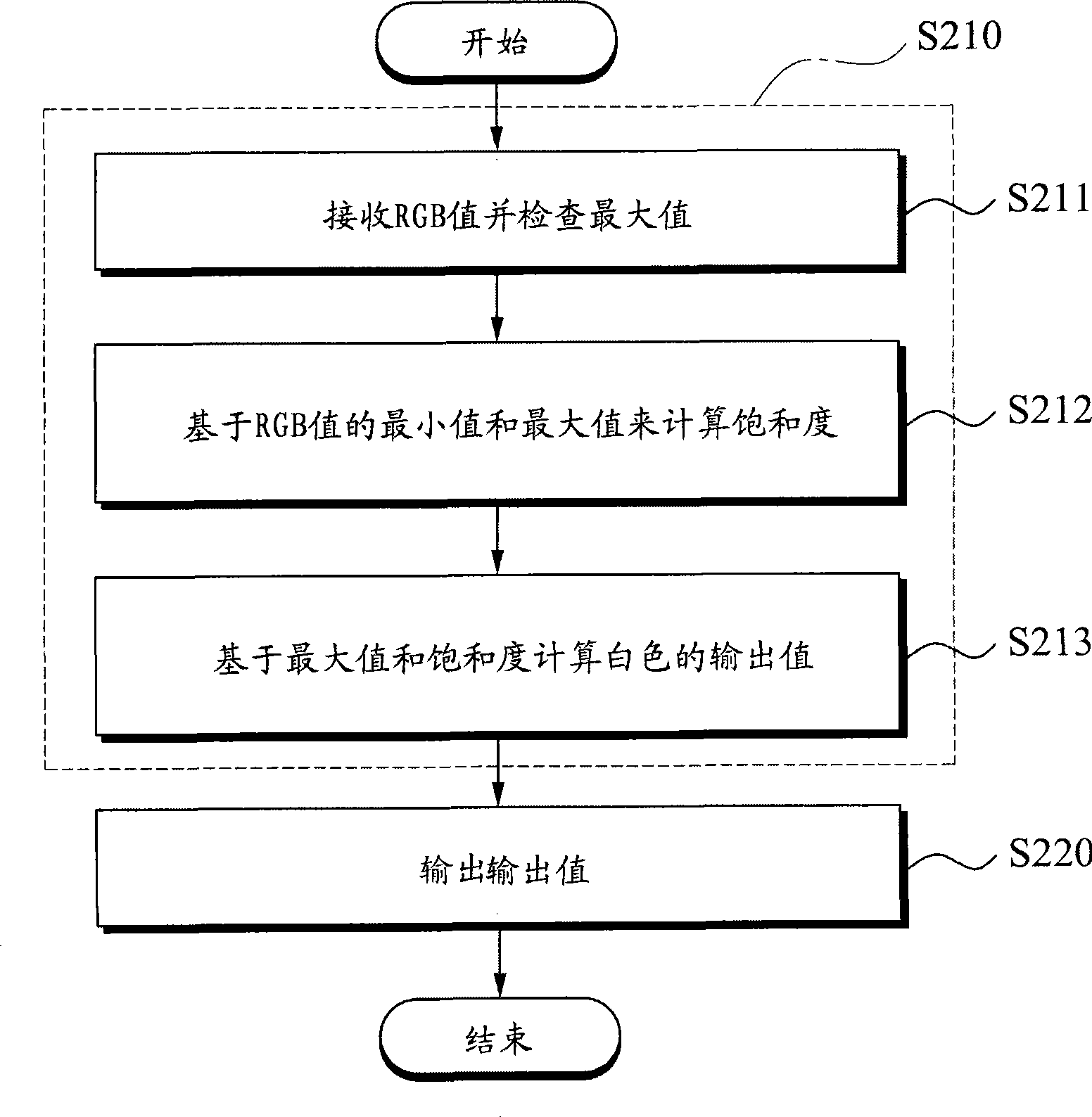
A Red Green Blue-to-Red Green Blue White (RGB-to-RGBW) color decomposition method and system. The RGB-to-RGBW color decomposition method includes: determining an output value of white based on inputted RGB values and a saturation; and outputting the output value when an input color is a pure color.

Description

[0001] This application claims the benefit of Korean Patent Application No. 2007-81229 filed with the Korean Intellectual Property Office on Aug. 13, 2007, which is hereby incorporated by reference in its entirety. technical field [0002] Aspects of the present invention relate to a color decomposition method and system from red, green, blue to red, green, blue and white (RGB to RGBW), more specifically, to a color decomposition method and system from RGB to RGBW, This method and system can be applied to all displays that use sub-pixels to represent images (transmission type displays such as liquid crystal displays (LCD) and plasma display panels (PDP), reflective type displays such as electronic paper (E-Paper), such as Photoluminescent systems for organic light emitting diodes (OLEDs, etc.). Background technique [0003] Conventional techniques include various methods of extracting red-green-blue-white (RGBW) signals from red-green-blue (RGB) signals. However, traditiona...

Claims


Application Information

Patent Timeline
Patent Type & Authority Applications(China)
IPC IPC(8): H04N9/64G09G5/02
CPCG09G2360/16G09G2340/06G09G2320/0209G09G5/02G09G3/3607H04N9/64
Inventor 郭永信朴柱容朴斗植
Owner SAMSUNG ELECTRONICS CO LTD
Learn More