Milling machine with disc brake base
A milling machine and disc brake technology, applied in the field of milling equipment, can solve the problems affecting the flatness of the processing surface, the movement of the frame in the horizontal direction, and the fixing of the frame, so as to achieve the effect of improving processing efficiency and milling accuracy
- Summary
- Abstract
- Description
- Claims
- Application Information
AI Technical Summary
Problems solved by technology
Method used
Image
Examples
Embodiment Construction
[0016] See attached Figure 4 to attach Figure 5 Shown, the vehicle frame 1 of bicycle comprises head pipe 2, upper beam pipe 3, lower beam pipe 4, standpipe 5, five-way pipe 6, cross fork 8, vertical fork 9 and cross fork 8 and vertical fork 9 junctions Disc brake seat 10, disc brake seat 10 has an opening 12 for erecting on the wheel axle of the bicycle, see attached Figure 4 And attached Figure 5 As shown, the side surface of the disc brake seat 10 close to the wheel of the bicycle is the joint surface 11 for assembling the disc brake pad.
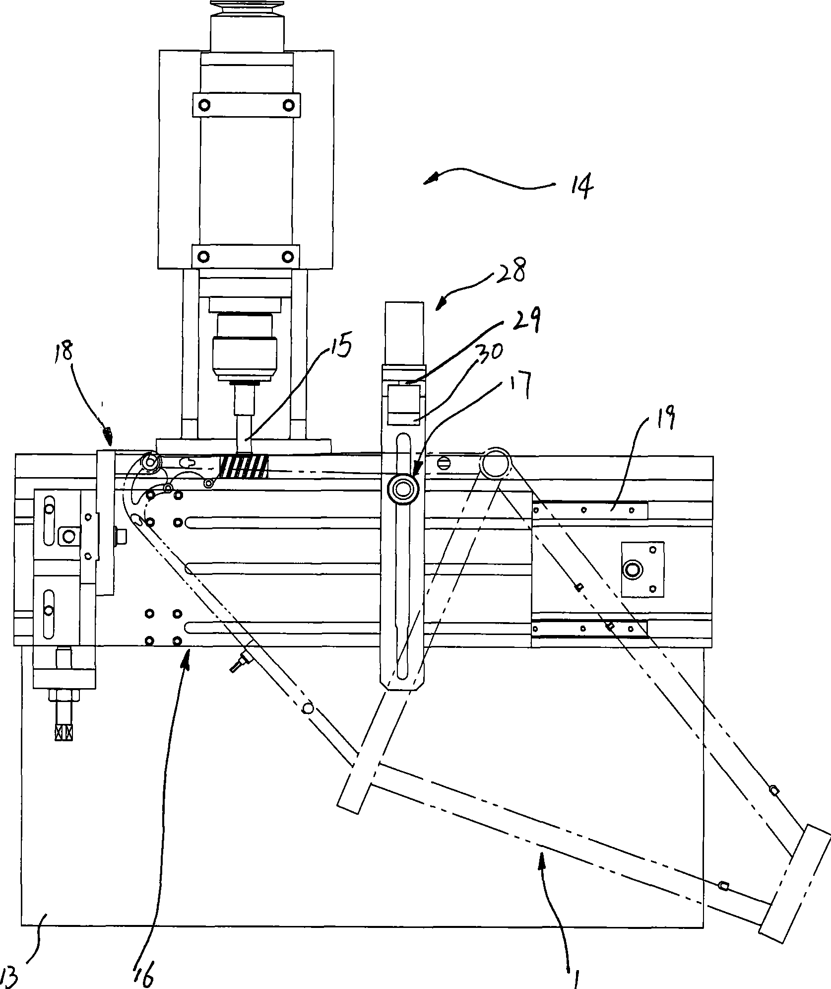
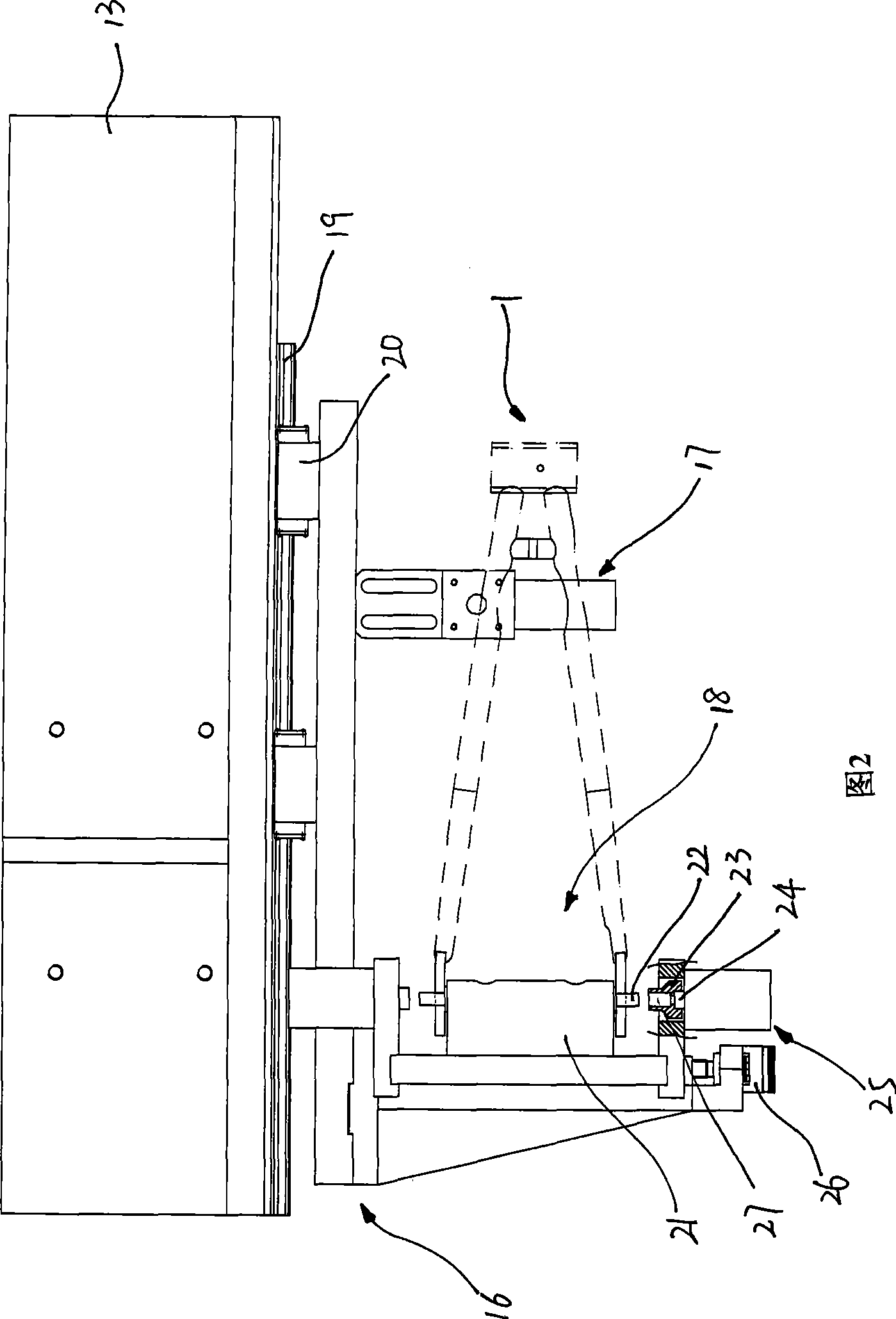
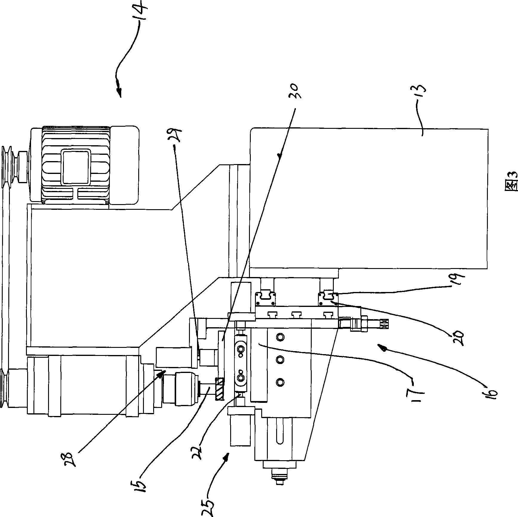
[0017] See attached figure 1 Referring to accompanying drawing 3, a kind of disc brake base milling machine, comprises frame 13, is arranged on described frame 13 and is installed with the machine head 14 of milling cutter 15, is positioned at the below of described machine head 14 workbench16. The workbench 16 is movably arranged on the frame 13, the workbench 16 extends along the vertical plane, and the workbench 16 is fixedly...
PUM
 Abstract
Description
Claims
Application Information
 - R&D
- Intellectual Property
- Life Sciences
- Materials
- Tech Scout
- Unparalleled Data Quality
- Higher Quality Content
- 60% Fewer Hallucinations
Browse by: Latest US Patents, China's latest patents, Technical Efficacy Thesaurus, Application Domain, Technology Topic, Popular Technical Reports.
© 2025 PatSnap. All rights reserved.Legal|Privacy policy|Modern Slavery Act Transparency Statement|Sitemap|About US| Contact US: help@patsnap.com


