Gear box suspension cushion
A technology for suspension cushions and gearboxes, which is applied in the direction of control devices, power devices, jet propulsion devices, etc., and can solve the problems of deformation of rubber materials, reduction of vibration isolation rate of suspension cushions, and impact on the service life of ride comfort components, etc. problems, to achieve the effect of avoiding conflicts, reducing deformation, and good limit effect
- Summary
- Abstract
- Description
- Claims
- Application Information
AI Technical Summary
Problems solved by technology
Method used
Image
Examples
Embodiment 1
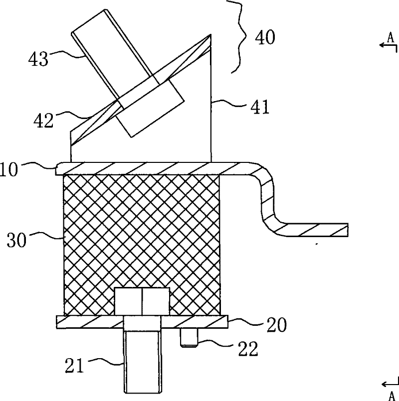
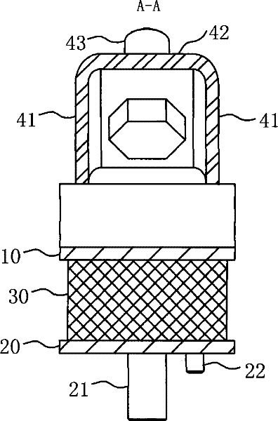
[0017] The plate body of the upper splint 10 located in the body bracket 50 and the members of the body bracket 50 are in a state of avoiding each other. The upper splint 10 is provided with a bracket 40 upwards. The upper end surface of the bracket 40 coincides with the installation surface of the gearbox. The lower splint 20 It fits with the lower bottom plate 52 of the vehicle body bracket 50, and the plate surface of the lower bottom plate 52 coincides with the mounting surface of the vehicle body, such as Image 6 shown.
[0018] combine figure 2 , 3 , 4, 5, 6, the plate body of the upper splint 10 in the body frame 50 is bent toward the side where the lower splint 20 is located, and is located in the space between the upper baffle plate 51 and the lower floor 52 of the body frame 50 Inside, the bent portion is in a Z shape, and the plate surface after bending is parallel to the plate surface of the lower splint 20 . The width of the upper splint 10 is approximately e...
Embodiment 2
[0021] The difference between the second embodiment and the first embodiment is that the plate body of the upper splint 10 in the body bracket 50 is bent toward the side where the lower splint 20 is located, and is in a mutual avoidance state with the body bracket 50, that is, it is in the body bracket In the space between the upper baffle plate 51 and the lower bottom plate 52 of the 50, the bent portion is L-shaped, and the plate surface after bending is perpendicular to the plate surface of the lower splint 20 . like Figure 7 , 8 shown. For the rest of the second embodiment, refer to the first embodiment.
[0022] In summary, the core of the present invention is to fasten and connect the powertrain and the suspension cushion through the bracket 40, and after the powertrain is double damped by the bracket 40 and the rubber body 30, the deformation of the suspension cushion can be effectively limited. At the same time, the plate body of the upper splint 10 located in the ...
PUM
 Abstract
Description
Claims
Application Information
 - R&D
- Intellectual Property
- Life Sciences
- Materials
- Tech Scout
- Unparalleled Data Quality
- Higher Quality Content
- 60% Fewer Hallucinations
Browse by: Latest US Patents, China's latest patents, Technical Efficacy Thesaurus, Application Domain, Technology Topic, Popular Technical Reports.
© 2025 PatSnap. All rights reserved.Legal|Privacy policy|Modern Slavery Act Transparency Statement|Sitemap|About US| Contact US: help@patsnap.com


